CAPSTONE 460
Visual Circuit Builder, January 28, 2018
Project Description: The design of a pedagogical(teaching) tool that provides a visual editor allowing users to build circuits of their choice and a means to follow the logic flowing through the circuit.
Capstone
BeginningsJanuary 28, 2018
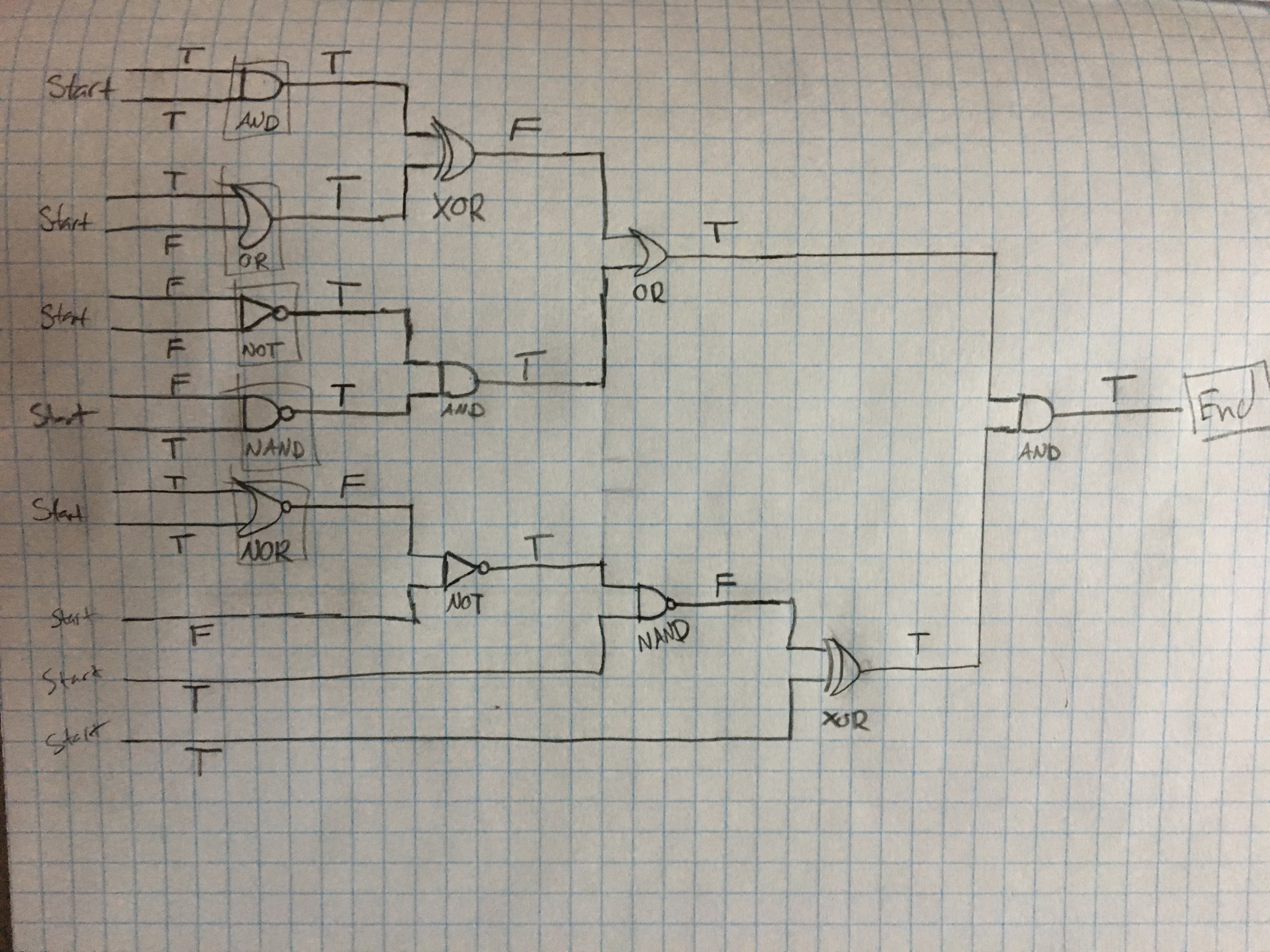
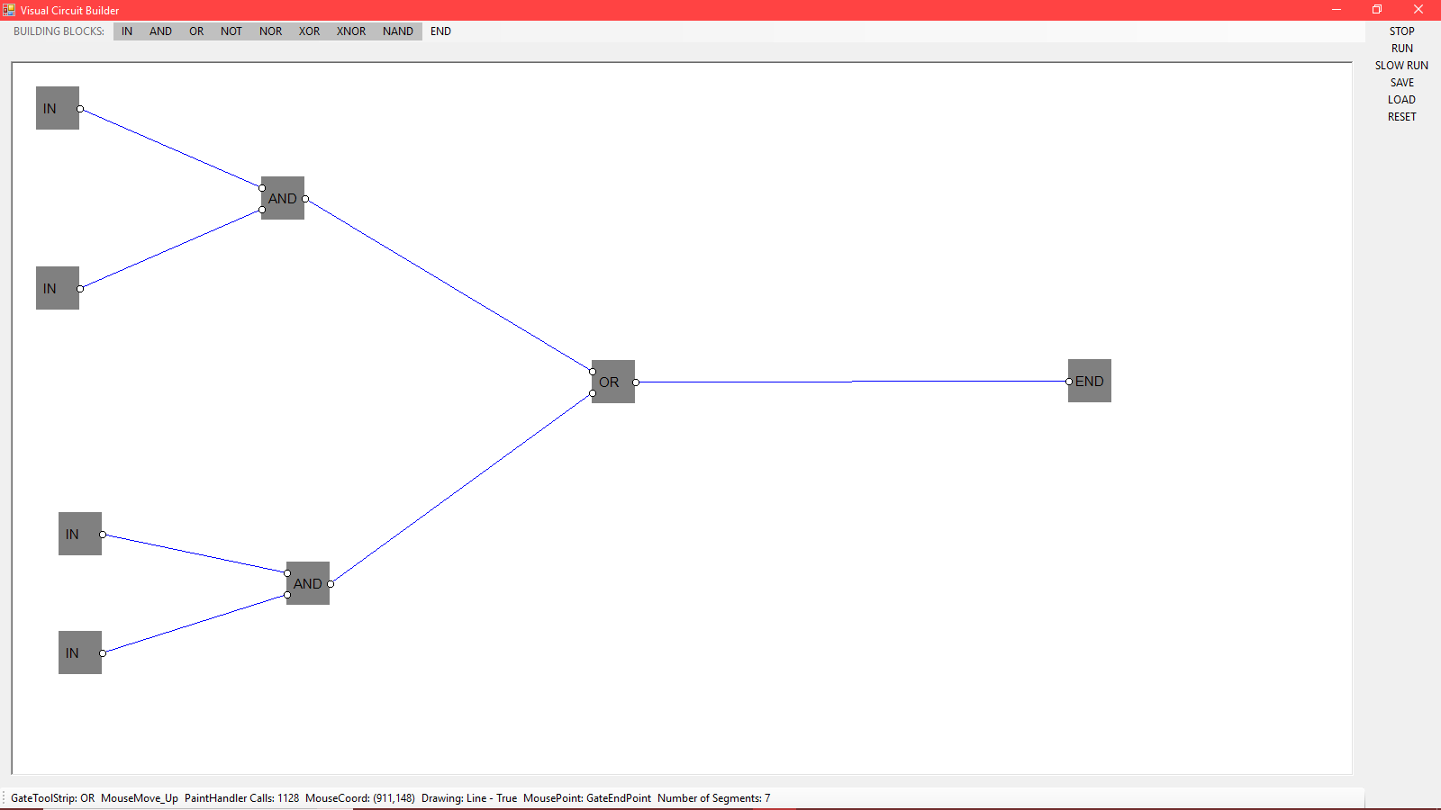
So to begin tackling this project I drew a simple logical circuit with AND, NOT, NAND, OR, NOR, and XOR gates. This example is what I would like the end result to look like. The gates are going to be images that can be dragged/dropped from a menu to a user interface. The lines are going to connect the gates with color differentiating true and false, ex: (REDLINE) = FALSE, (BLUELINE) = TRUE, these lines are going to be on the menu for selecting. There are many factors that I must address with these decisions, like multiple lines on a gate, gate flexibility, data structure, and a design that will follow the links and gates.
Capstone
Beginning of the Visual Part, February 4, 2018
Still working on the visual aspect of the program. I so far have a menu strip were the user can choose which logical operator they want. When this happens the wanted logical operator appears on a reserved spot on the screen. I have also implemented a grid and plan to implement a snap feature for clean structures. The data structure for the visual part of the program I'm still figuring out. So far not much progress I plan in having a well implemented drag/drop feature by the end of the week on Friday.
Capstone
Beginnings February 12, 2018
1. Representing the Circuit: in dealing with saving the circuit. Using an array of nodes to save to a file would be good. For example the first line of the file would represent a node. Line1: id:AND,(X:45,Y:50),previous:START, next:XOR. 2. Using trees to perform logical operations on the circuits. Method to traverse the tree: BFS, DFS, etc. 3. Plan for the next couple of days: create a way to connect two gates with a line (while constantly drawing the line).
Capstone
Building Visuals, March 4, 2018
So far I can draw lines and gates on to the screen. The user can modify the length of the lines with a mouse_click and _drag, the user can also move an entire segment with the same method of mouse_click and _drag. The gates on the screen can also be moved this way. As for other features, I programmed a simple snap fcn where the mouse will snap to the endpoint of a line making the use of the program easier for the user.
This weeks goal: program a snap fcn to the gates endpoints, this is going to be done using some math, because all the gates have the same dimensions. So all I really need is the (x,y) coordinate of the gate, then check if (x+12)(y) is the (x,y) coordinate of a line too, and repeat this process with (x+36)(y) and (x+64)(y+24).
Another goal for this week: Then after I get the snap fcn working, I can work on dragging both a gate and any endpoints connected to it. This would be done with if statements and redrawing any lines which are connected to the gate, as the gates (x,y) coordinate changes, change the endpoint connected by that degree as well.
Another goal for this week: Overlay an image over the rectangle on the screen.
Capstone
Building Data Structures and leftover visuals March 25, 2018
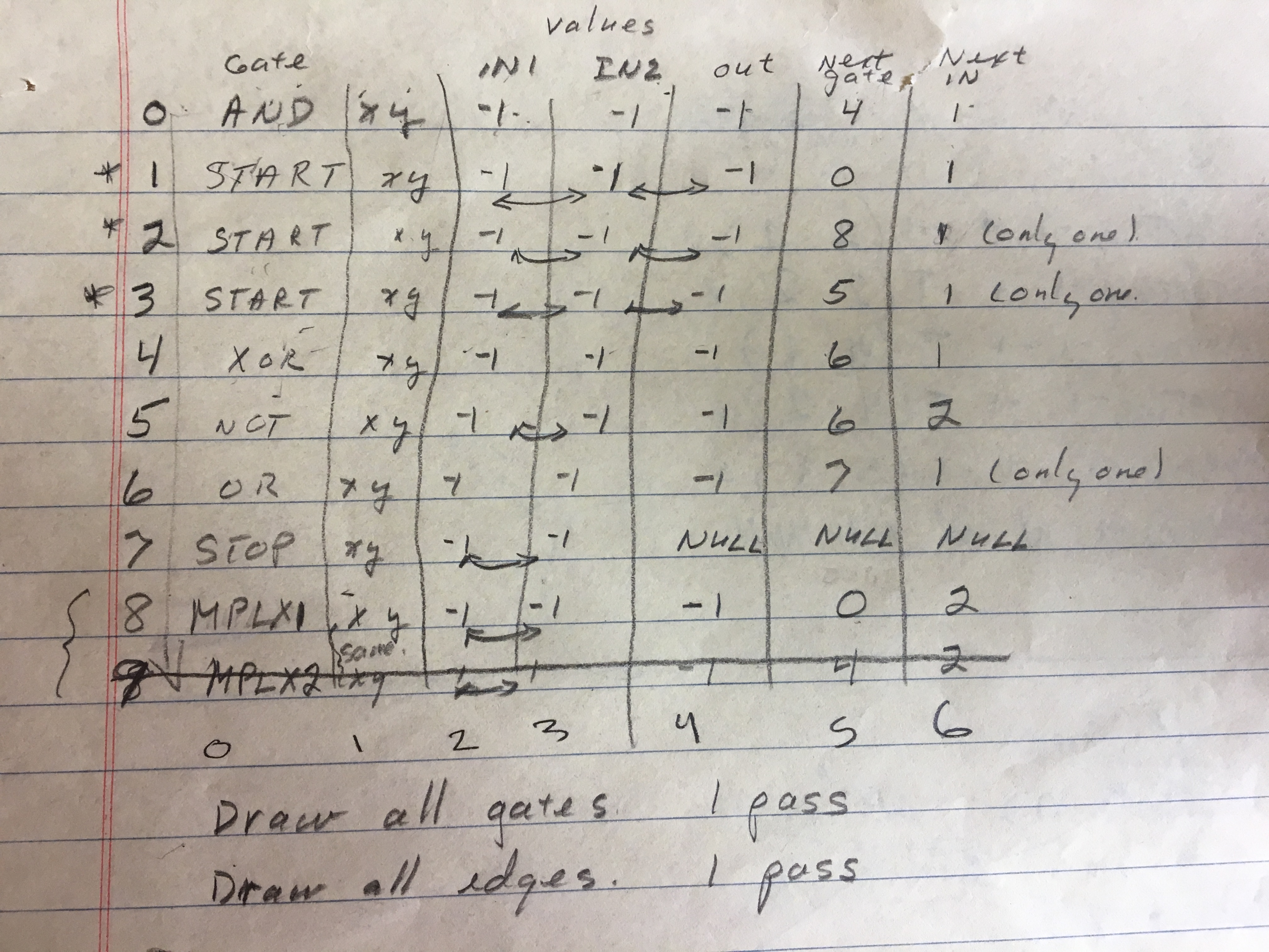
I have finished most of the visuals expect for some minor things like; gate string identifications, and deleting items. Now I'm going to continue onto the data structure part and the logic data structure of the project. I'm not were I would want to be in the stage of the project so I've decided to set daily goals to complete and to fasten the pace of the project. Monday's Goal: get different gate identifications and be able to delete an item like a gate. Tuesday: I want to change the data structure of the program to nodes and have it still functioning. Wednesday: Get a file to paint gates onto the canvas. Thursday: Get the file to connect the gates via lines. Friday: Re-look at code and solidify it, check for errors and such. Saturday: documentation. In more detail: for the file data structure I'm going to use a table with values: ID:gate,Position(x,y),bool:in1,bool:in2,bool:out,NodePointer:nextg,string:nextIn. I've built a circuit and saved a circuit on paper using this table so, I'm pretty sure this will work. Worries: I've tried deleting a gate using the table and it turns out troublesome; creating holes, so I will create the table once the user finishes creating their circuit. I will leave the nodes to deal with deleting. After this is in place I think I'm going to use queues to perform logical operations.
Capstone
Building Data Structures and leftover visuals cont. March 27, 2018
So after working yesterday, I realized that to implement the goals for Monday, I need to change the data structure to nodes first. Also probably not gonna implement a drag/drop feature were the user can drag a gate onto the canvas, because it's not a requirement and you can't set picturebox.allowdrop = true;. I'm going to focus on switching the lists to an array of nodes. Also, I want to present something were my peers can give a lot of feedback on, given that my visuals are only a portion of the project. I've also realized that I still need an input and output gate with only 2 or 1 endpoint. As well as the gate NOT with its 1 input and output.But to do this I still need to change my data structure to nodes, so I know what to paint in the paint handler. So along with Wednesday's goal I'll add the gates as well.
Capstone
Building Data Structures and leftover visuals cont. March 28, 2018
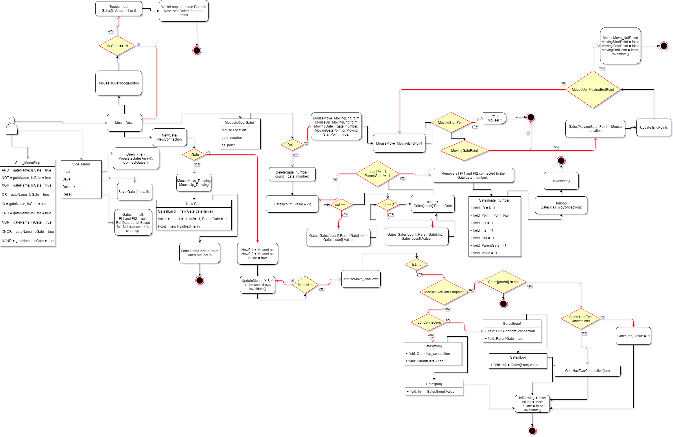
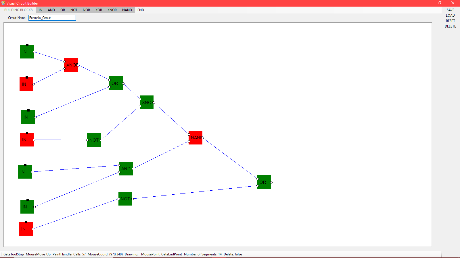
Got the program to work with a class called Gates, which contains an ID, Point, In1, In2, Out, NextGate, NextIn. The program now reads the point and draws it to the screen, and using the point with some math the program draws the connections, also I can distinguish uncommon gates like IN, END, NOT which do not have three connections. I've decided that the program should deal with drawing lines in a separate way than it draws the gates. My PaintHandler draws all the gates first using an array of Gates, then runs through a list of points and draws the lines and its endpoints. Now with the program running on a class I can move onto having a file paint circuits onto the canvas, and writing from the canvas.
Capstone
Building Data Structures and leftover visuals cont. April 1, 2018
So I got the program to paint a circuit from a file, thanks too Dr. Pankratz, then the user can add to the circuit. I haven't got the program to delete gates and lines that will be done soon. I don't have any progress towards the logic flowing of the program, but I'm thinking about "cheating" in a way, instead of calculating and following the logic, I'm going to solve the entire circuit in Gates[] and then just display the flow of the logic using some fcnX which is probably gonna be a queue, I just have to know where my STARTS are. This weeks plan: Monday, get deleting gates and line. Tuesday, write the array of gates to a file, and be sure to know what Gate the users are connecting together by updating NextGate and NextIn in the MouseEventHandlers, which shouldn't be to hard because, I can snap to an endpoint already so I know what gate the mouse is over. This will probably take more time than I am allocating, so I'll leave Wednesday open for that as well. If I can get everything to work, I'm also going to program a copy and past fcn.
Capstone
Building Data Structures and leftover visuals cont. April 5, 2018
Hello Again, so updates: instead of updating the data structure in the MouseEventHandlers I've decided to create a fcn that will
go through all the data; the List
Capstone
Presentation Day. April 26, 2018
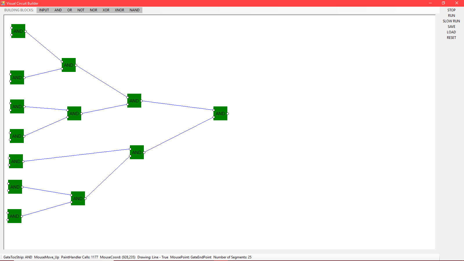
It's been some time since I've posted another blog, but the presentation went pretty good. The user can build circuits and execute them. On top of that the user can save their circuit to a file on their computer. They can also use this saved circuit later to build upon or use it on other circuits. I also want to give credit to Rob Stephens program howto_line_editor which I used as a skeleton for my program, his program contained the mouse events I needed and it really helped me out.

Victor Garcia
Just me, myself and I, exploring the "400 Capstone Project." A little about myself, I'm a first generation college student with a Hispanic background, I love soccer, Jesus, food, learning, and using my reasoning well. I recently became a fan of St. Thomas Aquinas, his systematic way of arguing really appealed to the CS in me. My personality is a quiet one, I enjoy challenges and look forward to the future. I enjoy playing video games because they stimulate my brain. In my recent years as a computer science student I can say I looked forward to the Capstone. To dedicate oneself to a single project that takes the course of a semester sounds thrilling.
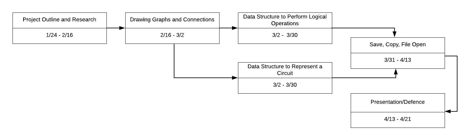
Pert Chart
A simple Pert Chart to represent how I plan on dividing my work throughout this project. Everything is capable of change, hopefully not. Also it is not represented in this chart but I am thinking about how everything will affect each other.
Victor Garcia
Philosophy Statement: My purpose in pursing computer science is to enrich my mind with structure and creativity. I believe thinking in a logical manner is of the utmost importance since logic is the most compelling and persuasive form one can use to explain and understand. I wish to work in furthering logics boundaries and wonders on a hardware, software, and spiritual level, to perfect the art of structure and to apply it to my life as much as I can.