Use
Hints
Exceptions
Philosophy
Project Files
|
Welcome Welcome to Chris Frohliger's project page. I had a lot of fun working on this. It was much different than anything that I have ever done. I have gained new knowledge on the hardware aspect. Project Definition Laser Lights Name: Chris Frohliger Project Description: Construct a driver that controls movement of a laser light beam, and develop applications for it. General Requirements: 1. Identify all equipment and costs to satisfy the requirements, trying to minimize costs. (1.5 weeks). 2. Order and build the necessary hardware and circuits. 3. The driver will turn the laser on/off. 4. The driver will rotate the laser on an axis when sent parameters like speed and angle. 5. Add another axis to the laser's movement. 6. Develop two interesting applications for the driver. (e.g. music, drawing) Detailed Requirements: 1. Laser pen dissection found in Model Railroading. Top Hook-up and Installation There are two parts to the hook-up and installation of the laser projection system. The first part is the actual connecting of the hardware to the computer. The second is setting up the software. Part one: The hardware There are three pieces of hardware all with an associated board. There is the plywood section that contains the motors, mirrors and laser. There is the breadboard section which contains the wiring. And finally there is the parallel port board which is the part that connects to your computer. Step 1: Check to see if the parallel port board and the breadboard are connected. The parallel printer board and the breadboard should already be connected. If they are skip to Step 3, but if for some unfortunate reason they are not, continue to Step 2. Step 2: Connecting the parallel port board to the breadboard. Use the below picture for a reference while working on this step. 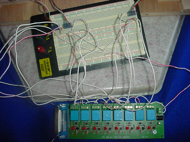 The parallel port board is on the bottom while the breadboard is on the top. You will notice that on the parallel port board there are eight blue relays. They are also numbered on the bottom of the board, one is on the side where the parallel cable plugs into the board, while eight is on the side where the power comes into the board. Only the first six relays are used in controlling the motors. You will see that each of the first six relays has two long wires coming out of it. These wires are connected to terminals labeled NC on the left and NO on the right. These stand for Normally Closed and Normally Open respectively. There is also a wire coming out of the right side connected to a terminal marked +12. Your board should look like this. 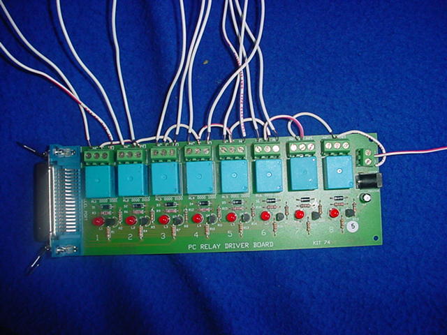 If you turn your breadboard so that the three knobs are on the left, then near the top you will have three black sets of male pins, two fairly close on the left and one on the right. There is a wire going to the third pin from the left on each of these sets of male pins. This is positive wire that goes to each of the motors. These positive wires all meet on one column. The below picture is how it should look. 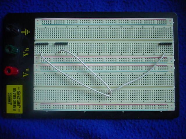 In the following instructions I will use the notation 1NC to represent the wire connected to terminal marked NC on the relay furthest to the left on the parallel port board. 2NO would represent the terminal marked NO on the second relay from the left and so on. On the breadboard I will represent the three sets of pins as Left, Mid, and Right. The actual pin will be counted from the left on the set. So the wire that goes to the set of pins on the left would be denoted Left3. Here is a table of all of the connections that must be made:
Step 3: Check to see if the plywood section is assembled. If the plywood is assembled there will be three motors on it, as well as the large mirror assembly. If the plywood section is assembled then skip to step 5. If not then proceed to step 4. Step 4: Assemble the plywood section. The completely unassembled plywood section will look like this. 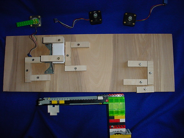 There are three motors, one with a Lego attached to it, and the other two with just gears attached. The first step in assembling the plywood section is to put the motors in their places. The one with the Lego attached goes in the lower left area. The shaft of the motor will be parallel to the base and run from left to right. One of the other motors is placed in the area with the stack of paper on it. It has its shaft parallel to the ground. The third goes in the area that is in the lower right area. It has its shaft perpendicular to the ground. When placing the motors they should be positioned in such a way that the leads are coming off in the direction indicated in the photo below. 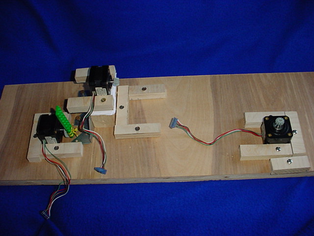 The next step is to attach the mirror assembly. The large, flat, black panel, on the mirror assembly, goes in the slot that is below the motor on the left. And the flat white piece on the mirror assembly goes in the area next to the motor on the paper. The gears on the motors should line up with the gears that are attached to the mirrors. You can test that they are lining up correctly by turning the gears attached to the motors with you finger. If the mirrors also turn, then they are aligned correctly. If the motors are not correctly aligned you can move then a little bit or apply gentle pressure to the mirror assembly to move the gears next to the ones attached to the motors. Below is what the plywood section will look like once correctly assembled. 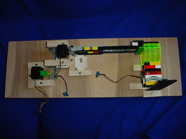 Step 5: Connect the plywood section to the breadboard. The three motors need to be connected to the breadboard. This step will use the same numbering system for the pins as was used in step 2. On the leads coming from the motors, the black wire is the one that will get connected to the positive wire. The brown wire will get connected to the pin number 1 while the white wire will get connected to pin number 6. The lead connected to the shutter motor gets connected to the Left set of pins. The lead from the motor on the paper gets connected to the pin set in the Middle. The lead from the motor on the right gets connected to the set of pins on the right. The section of Lego that the laser is connected to, can now be positioned on the plywood so that the laser shines past the shutter and onto the small mirror. The assembly should look something like the photo below once this step is finished. 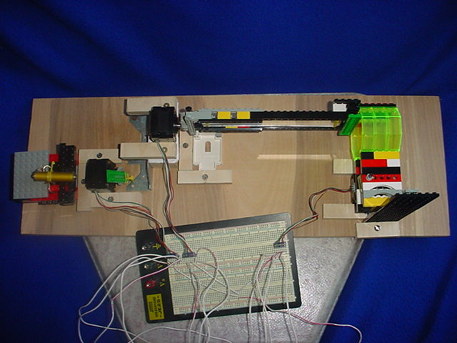 Step 6: Connecting the assembly to the computer. The parallel port board gets connected to the computer through the parallel port. Connect a parallel cable to the parallel port on the computer. Now connect the other end of the cable to the parallel port board. Power needs to be supplied to the board. Plug the power transformer into on outlet. Now connect the other end to the parallel port board. The motors will now be locked and only able to be turned by running one of the applications and using the adjustment buttons to adjust the mirrors and shutter. Part two: The software Step 7: Installation of the software. Installation is easy. All that is needed is to copy the exe’s for the programs into a directory. You also need to have a copy of the file 8255.dll in the directory. Now you may run either of the programs. You may need to adjust the laser, mirrors, and shutter to get best results. Tip: Adjusting the assembly When adjusting the assembly using these rules usually lead to pretty desirable results. The first thing to adjust is the shutter. When looking from behind the laser, the shutter and laser should be adjusted so that if the shutter where to move one click to the left, the clockwise button, the beam would be blocked. Now the smaller mirror should be adjusted. It only has about ten positions that it can be in where it projects the beam onto the long mirror. For the wall saver application the smaller mirror should be adjusted until it can be clicked five clicks in either direction. For the drawing application there is no good rule of thumb for the position this mirror should be in, it depends on the picture that you drew, it is best to adjust this mirror after you start running the drawing. The last thing to adjust is the long mirror. This one you can adjust until you are happy with the vertical position of the laser. Unlike the small mirror, the long one has quite a few acceptable positions. Top Use There are two programs included with this project. The first is a kind of screensaver for your wall. If you start the wallsaver.exe application you will be presented with a small window containing eight buttons. There is a brief description of their function below: Start: When this button is pressed, and if all of the hardware is correctly attached to the computer, the laser beam will randomly move about on the wall. Stop: Clicking this button while the mirrors are moving will stop them. It does not reset any of the internal values used to keep track of the lasers position, so the mirrors can be restarted and will remain in the same relative area that they were calibrated to before stopping. Up: This will move the laser up. This button is used for calibration. Down: This will move the laser down. This button is used for calibration. Left: This will move the laser left. This button is used for calibration. Right: This will move the laser right. This button is used for calibration. Counter-Clockwise: This turns the shutter counter-clockwise when looking at it from the side that has the Lego bumps facing out. While running this is the direction that the motor will be told to go if it is asked to turn on the laser. Clockwise: This turns the shutter clockwise when looking at it from the side that has the Lego bumps facing out. While running this is the direction that the motor will be told to go if it is asked to turn off the laser. For this application the shutter should be adjusted so that it is not interfering with the beam. This can be done by clicking the counter-clockwise button until the shutter is not in the way of the laser. When adjusting the horizontal position of the laser it is important to center the beam, by number of click from either end not position, on the longer mirror. This is because there are only about 10-12 different positions that the horizontal mirror can be in that will successfully project the beam. The vertical position of the beam can be adjusted to your liking, with in some reason. The second program one that moves the laser in a path that is specified by the user. Here is a short description of the eleven buttons eleven buttons: Start: When this button is pressed, and if all of the hardware is correctly attached to the computer, the laser beam will randomly move about on the wall. Stop: Clicking this button while the mirrors are moving will stop them. It does not reset any of the internal values used to keep track of the lasers position, so the mirrors can be restarted and will remain in the same relative area that they were calibrated to before stopping. Up: This will move the laser up. This button is used for calibration. Down: This will move the laser down. This button is used for calibration. Left: This will move the laser left. This button is used for calibration. Right: This will move the laser right. This button is used for calibration. Counter-Clockwise: This turns the shutter counter-clockwise when looking at it from the side that has the Lego bumps facing out. While running this is the direction that the motor will be told to go if it is asked to turn on the laser. Clockwise: This turns the shutter clockwise when looking at it from the side that has the Lego bumps facing out. While running this is the direction that the motor will be told to go if it is asked to turn off the laser. Clear: This button clears the drawing area so that a new drawing can be entered. Clicking this button also resets all for the internal flags that prevent you from adding more dots one the drawing has been run. Save: This will save your current drawing. You are only able to save one drawing at a time. Load: This loads the last drawing that you saved. After loading you are able to continue editing the drawing. If you wanted to continue editing your drawing after you have run it, you can save and then load. You will now be able to continue editing. Start: This will start drawing your drawing on the wall. If you have already started and stopped, it will start up where you left off. Stop: This will stop the mirrors and shutter from moving. If they are currently not running then this button is ignored. The best way to adjust the mirrors for this application is to start it drawing and then adjust the position to where you want it. Remember that you will not be able to adjust the horizontal position very much. If there is an edge of your drawing that is not showing up this is most likely being caused by the mirrors turning too far so you will need to adjust the mirrors. Top Hints -When setting up the plywood base, make sure and test whether the gears are making contact by turning the one attached to the motor with your finger. -There is less distortion if you position the plywood base so that the long side is parallel to the surface that you will be projecting onto. -With the drawing program, using smaller pictures gives a more solid appearance to the lines that the laser is tracing. Top Exceptions -In the drawing application. If you end on the starting point with a different shutter position that you started with, the shutter will not do what it is supposed to and will start to spin in one direction. Top Philosophy My philosophy includes the following: There is never such a thing as too many function. There is never such a thing as a good global variable. Why name a variable ‘A’ when you can name it ‘intNumberOfDoughnutsEatenByHomerSimpson’ Twenty minutes of paper and pencil will save you an hour of keyboard and monitor. There is never such a thing as too general a solution. Use the right tools, you wouldn’t use a hammer to clean a window would you? Just because something is easy doesn’t mean it isn’t powerful, it is just well designed. If you don’t document your code, I am not going to read it. One mans solution is another mans confusion. Top |