JARED WIESMAN
  • Home
  • About Me
  • Capstone Blog
  • Home
  • About Me
  • Capstone Blog
Search

Final Thoughts

5/7/2019

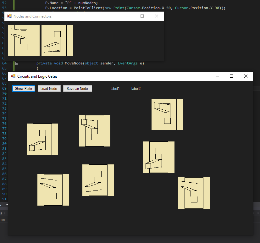
After almost a month without a blog post, my project is officially wrapped up. Before presentations, I was able to successfully implement a delete function, a system to step through the circuit, a clear function, and a slightly more user friendly workspace. Overall I'm happy with where my project got to. There's always a few things I'd like to change but I'm proud of the work I got done. In its current state, I believe my Visual Circuit Builder is ready to be used as an effective pedagogical tool as it was meant to be.
Final
 

Files: Writing to and Reading from

4/11/2019

A big couple of days for my project and I. After countless pages of scribbled notebook paper and many hours debugging, I can successfully write to a file and read it back in. Normally this isn't a difficult task, but I wanted to allow users the option of having previously added nodes, either from a file or placed manually. This meant that the ID values stored in my files have to be adjusted when being read in so that there's no conflict between previously placed nodes and the new imports. It was much harder than I expected, and I still expect some issues with it when I add the ability to delete a node, but for now it works very well and is fairly efficient.
Reading From File
 

Displaying Output Graphically

4/9/2019

The relatively easy task of changing node colors was made more difficult by my thinking ahead to the future. One of the requirements of the project is that I step through the logic one node at a time. This means I can't color the nodes recursively down the tree and I'll have to either revise my CalcOutput function or write a similar one that checks for a toggle. With that in mind for the future, I created a funtion that recolors the nodes based on their output value. This works very smoothly and shows no lag or flickering. I also properly implemented the "OUT" node in the form of a lightbulb. This node has one input and no output. The next step for me isn't super set. I could work on saving to and reading from a file, moving nodes once placed, improving the visuals when dragging a node, or stepping through the output. In any case, my project is now completely useable and accurate.
Colored Nodes
 

Connecting Nodes Graphically

3/31/2019

I had always envisioned wires in this project as being a draggable thing that would snap onto nearby nodes. Working on it, I realized just how hard that would be to implement and how tedious it might be to use. During walkthroughs, I was given the suggestion of connecting nodes by clicking on them. The best way to implement this, I decided, was to make several states that my node MouseDown handler would look at. The states are Move, Connect, and Test. Connecting nodes is done simply by clicking the child node (output) and then the parent node (input). Once connected, the wire is drawn in the correct color based off of the child's output, and recursively computed through the "tree". The gif below shows how the Test state works, clicking nodes to view their status, and clicking SWITCH nodes to toggle their output. The next step is changing the other nodes' pictures based on their output.
Working Wires
 

Multiple Outputs and Final Node Designs

3/25/2019

While trying to set up my class to accomodate for multiple outputs, I found an issue that would prevent me from creating loops and clocks. After discussion with Dr. Pankratz today, I decided to default the output of a node to false instead of forcing two inputs before an output is given. In the meantime, with the help of my sister, my final node designs are done and imported into my project. There is no "wire" image because I plan on drawing the lines based on two endpoints. Once I implement the new logic and multiple outputs, I will be able to solely focus on getting the graphics to work correctly.
Clean Code
 

Properties

3/10/2019

While this overall was an unproductive week for my project, my Circuit, Node, and Wire classes are now reformatted courtesy of Dr. McVey. Using properties instead of accessors and mutators allows a much cleaner look to the code, both in the class and in its use. Apart from that, I took some time this week to plan the final look of my graphics and how I'll be able to connect wires to nodes, specifically when they aren't in the usual format (loops).
Clean Code
 

Classes and Functions

3/3/2019

Finally a breakthrough! After over a week of miscellaneous bug hunting and troubleshooting I'm fairly confident that my Circuit, Node, and Wire classes are correct and ready to be put to the test with graphics. There are still a few unknowns, such as how to reference them based on pictureBox ID, but I don't anticipate that to be too difficult. I may have to make the classes more robust in the future (more data checking), but the logic works for now. The screenshot below just shows a sample circuit I set up for testing and displays the six elements of the Node object I clicked on.
Classes Working
 

Classes and Functions

2/26/2019

The last two weeks have been spent writing and structuring my Circuit, Node, and Wire classes. In addition to constructors and accessors, I wrote funtions to add a node to the circuit, add a wire to the circuit, connect two nodes with a wire, and calculate the output of a node when both children are active (done recursively up the tree). I believe these funtions will allow me to test my classes independent of the visuals. Once the logic is tested, I can continue to work on the view of the form.
 

Mini Poster Board Sessions

2/14/2019

Today we had mini poster board sessions. I learned a lot about other people's projects, and was given a few good ideas for mine as well. One of the ideas that really stood out to me was making a 'wire' object to connect the nodes. Up until now I was unsure of how that would work and what the difficulty of that would be, but after today I'm feeling much more at ease.
Poster Board Drawing
 

Dragging and Dropping

1/30/2019

After hours of trial and error, my dragging and dropping works. Thanks to some small but crucial help from Mr. John McGorey, I can drag an image from one form to another and dynamically create a pictureBox at the drop location. While I was tinkering around with this I also figured out how to set up the SWITCH toggle for the true or false inputs and how to move a placed pictureBox. I need to clean up the moving of the pictureBoxes still but the next step for me is to create my backend Node and Circuit classes so I can start implementing and testing the logic of the circuits before trying to visually create the circuits and test it that way.
D&D
 

Creating Trees

1/28/2019

After deciding that a tree would be the best data structure to store my circuits in, I began looking into the best way to store them in a file. The best way I found was to use CSV(Comma-Separated Values) on multiple lines. Each line represents a node and the four values on the line are:
<Id>, <Parent Id>, <Node Type>, <Output State(T or F)>
This format allows me to have as many nodes as I need with infinite Ids. The node types are limited to the following (for now): NOT, AND, NAND, OR, NOR, XOR, and SWITCH. As I progress, I want to be able to save custom nodes and use them as well. Now that my website is published, the next step is becoming familiar with C# alleviate some hassle down the road.
Mock Tree
 

First Steps

1/26/2019

On Wednesday we were all assigned our projects for the semester. Upon reading mine, I was excited to get started but unsure of the best place to start and what direction to head in. After a talk with Dr. Pankratz I decided that the first step of the semester (besides getting this website up and running) is to find the best data structure and file format for my project. He suggested a reverse/sideways tree to represent the flow of the circuits and I think that's a good idea. The next step is to find a way to store that in a file.
  • Home
  • About Me
  • Capstone Blog