LightSync Hardware Components
The LightSync project includes a standard x86 computer dedicated to light control, a general-purpose computer for playing music and initiating light sequences, and some specialized control circuitry.
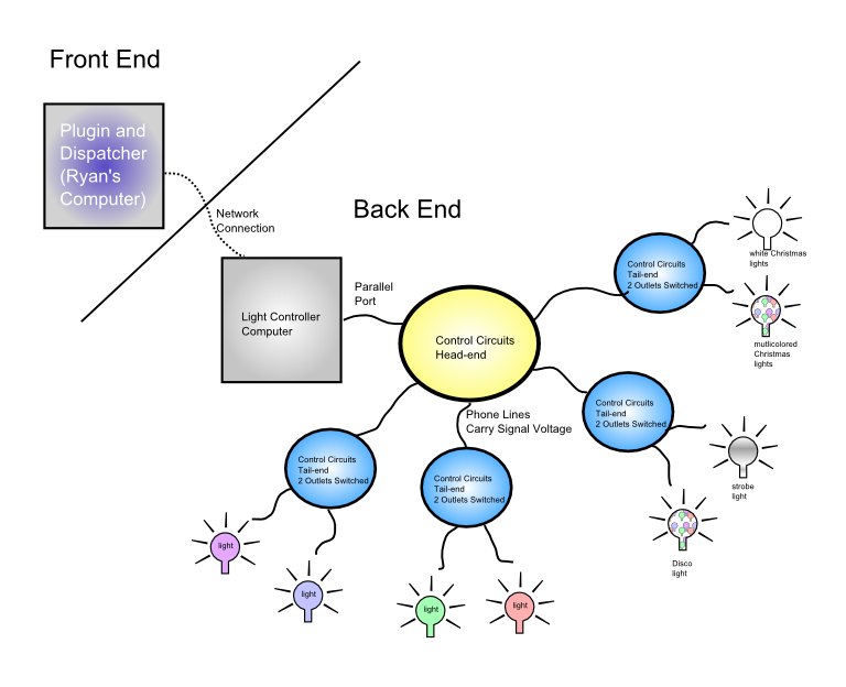
General Architecture
The LightSync hardware can be split into two major parts, with one of these parts divisible into three sub- components.
- Front End
- A commercial off-the-shelf (COTS) Linux-based x86 PC running Rhythmbox (a music library and player) and a custom plugin. More specifically, Ryan's computer.
- Back End
- Light Controller Computer - A low-spec, "throwaway" x86 PC, running a minimal Linux system and custom LightSync server software. Interfaces with front end via networking, with control circuitry via parallel port.
- Control Circuit Head-end - A custom set of circuits that isolate and amplify the signal from the light controller computer parallel port to trigger the tail-end circuits. Maximum voltage: 18 VDC.
- Control Circuits Tail-end - Actually several identical outlet boxes that connect to the control lines of the head-end and switch the wall current (120VAC) flowing to an outlet. This is the only place that high- voltage electricity is present in the custom circuitry, for safety reasons.
Each of these sections is discussed in more detail below. A summary of the signal path for an example light control command is described just below the diagram.
Architecture Diagram
Click the image for an enlargement
Signal Path
Signal processing software first processes a song to produce an event list of light changes. The software and hardware discussed here take that pre-determined file and "execute" it or play it back. The complete signal path to light up a single channel is as follows:
- The light track saved and played back on the front end computer dictates that a channel needs to be turned on or off.
- The channel is associated with a particular back end light controller computer and a full byte (8 channels) (discussed in the software section).
- The full byte for that controller is sent over the network to the light controller computer.
- The changed bit is output as part of the full byte on the parallel port of the back end light controller computer.
- This parallel port signal is isolated by the head-end control circuits, and amplified to 12-18VDC.
- The 12-18VDC signal passes over a telephone wire signal line to the tail-end control circuit for that particular channel.
- In the tail-end control circuit, the change in voltage on the signal line causes the relay to turn the power to the outlet on or off.
Front End
The goal of the project included being able to run a light show automatically with music playing on a regular computer. Due to the ease of software development when dealing with open source, Rhythmbox (a standard Linux/GNOME music library app) was chosen as the player to extend. This works out well since Ryan uses Rhythmbox to play music. As one might suspect, however, as much faith as we had in our circuit designs, we did not want to connect any circuits we built directly to his computer. For this reason, and for reasons of extensibility (discussed in the software section), only the "dispatcher" software runs on the front-end computer, which is connected to the rest of the system via standard computer networks. This provides protection against human error or hardware failure and avoids potential damage to Ryan's rather expensive computer.
Back End: Light Controller Computer
The somewhat risky position of being the system directly connected to the custom circuits is thus forced on a spare, disused computer. It is a standard HP Vectra with a Pentium 166MHz MMX processor, from around 1996. The hardware specs of this machine are hardly important, as its sole task in life is to listen to the network for incoming light change requests (discussed in the software section), and output the appropriate byte to the parallel port. The parallel port is a legacy (that is, not commonly on new computers but has been around for ages) port which was frequently used for connecting printers. In addition to some status signal lines, the exciting part of the parallel port is that it has 8 data lines used for sending a single byte (8 bits) in parallel (hence the name). The presence of any other lines may be ignored and these parallel 8 lines can be used to control outside circuits. When a byte is sent to the port, its bit pattern remains until the next pattern is sent. In traditional usage, bytes would be sent to the printer or other device in a regular rhythm. However, if we simply send one byte at a time, we can independently control all 8 channels (by calculating the value of the byte which the bit pattern corresponds to). The parallel port is a sensitive device and is integrated into the motherboard on most machines (and is internal in nearly all cases) hence the importance of not burning it out on a valuable machine. This also is what makes the complex control circuitry necessary: any kind of surge or back-current must be prevented.
Back End: Control Circuits Head-end
The head end control circuits plug via parallel port into the light controller computer. The job of this box is to isolate and amplify the very low voltage signal from the parallel port to produce 12-18VDC signal lines which are capable of operating power relays or other methods of switching wall current. It actually contains 8 identical circuits with diodes, a resistor, and a transistor that prevent backcurrent as well as overcurrent (in excess of 5.1VDC), produces a proper input signal to be amplified, and amplifies the input signal to a 12-18VDC control line, respectively. Two signal circuits (thus four wires) are passed over each standard telephone cable leaving the control circuit box: though normal (two-line) phone jacks and cable are used for signal lines, none of this circuitry should be connected to the phone system! The use of telephone wire simply makes connection simple and means that standard, affordable cables can be used. There are four RJ-11 phone jacks on the head-end circuit box.
Back End: Control Circuits Tail-end
The tail-end circuits use relays to turn wall current (120VAC) on or off based on the voltage passing over the (telephone wire) signal lines from the head-end control circuits. Four identical outlet boxes comprise the tail-end control circuits. Each has a power cable to plug into an existing wall outlet, a phone jack to connect the signal lines from the head-end, and a double power outlet, with each outlet switched independently. Thus, the eight channels controllable via the parallel port are divided up into pairs of channels, with each pair controlling its own separate outlet box. This allows controlled lights to be located at a distance from each other and the head-end circuitry: only an ordinary power outlet nearby and a long enough phone cord to reach to the head-end are required. Inside the box, two relays capable of switching wall current are triggered by the signal lines, which are protected from back-current by isolation diodes.
Content copyright 2006 Ryan Pavlik and Nicole O'Connell. Portions of web design 2005-2006 Ryan Pavlik. This is not an official St. Norbert College web page - opinions expressed here are those of the authors, and St. Norbert College offers no warranty or indemnity for the instructions contained here. Do not attempt to follow these instructions to duplicate the experimentation of the authors: this may expose you to dangerous electrical currents. The steps listed here are for documentation only.