Signal Processing
Signal processing is how we can generate a series of light commands automatically from music. This is a look at what signal processing is all about. Digital signal processing was used in our project, since our input data (sound files) was already digitized and usable in that format. For most industry applications, the input is analog and so the engineer or designer has the choice of digitizing the signal and applying digital filters, or keeping all the processing analog. We will first discuss the intuitive application of these ideas to our project, then the more theoretical definitions behind it.
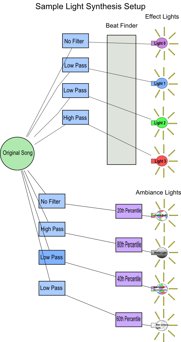
Sample Profile for Light Track Generation
click the image for an enlarged diagram.
The Process of Light Track Generation
A step at a time, for a single channel
- The light designer (us!) pre-specifies filters (low-pass: bass, high-pass: treble) to apply to the signal and the method for extracting light commands from the audio track.
- The light track generation software converts the sound file from a compressed format (MP3, OGG, etc) to an uncompressed WAV file for processing.
- If requested by the light designer, the software calls an external program to apply a filter to the WAV file. For instance if we want the light to turn on when there is a bass beat, a low-pass filter with a cutoff of 200hz would be applied.
- The filtered WAV file, as well as parameters (beat threshold, etc) are passed to the light command extraction program.
- The light command extraction program processes the filtered WAV file 1/43d of a second at a time, determining if the light should be turned on or off.
- The light track generation software takes the output of the command extraction program and merges it in to the light tracks, assigning it a channel (for instance, we could have just processed channel 2 on the switch).
- This process repeats starting at step 3 for each channel defined in the profile by the lighting designer.
Our Light Command Extraction Algorithms
The purpose of the light command extraction programs is to process an incoming WAV file and determine from it the timing of a single light channel turning on and off. It is called as an external program so that whatever language works best for this processing may be used, and so that flexibility and expansion is built-in. We have two light command extraction programs, each with their own purpose. They are the beatfinder and the percentile algorithm. Both consider 1/43d of a second at a time as a single instant - this comprises 1024 "samples" loaded from the file and allows calculation of the intensity, or relative sound volume and pressure, for a particlar instant in a song.
The Beatfinder

click the image for an enlarged diagram.
The beatfinder requires several values to be specified in the profile. pickup_c and dropout_c are constant coefficients that determine just how loud a moment in a song must be compared to its surroundings to be considered a beat. Rhythm, pickup_interleave, and dropout_interleave are values that specify how frequently a beat becomes a light change.
- Load an instant from the song, and store its intensity in the history (43 sample or 1 second history stored max).
- Calculate the average intensity over the last second (43 samples stored in history).
- If the light is off and the current intensity exceeds pickup_c * avgintensity:
- Increment the beat counter.
- Divide the beat number by rhythm and consider the remainder.
- If the remainder is equal to pickup_interleave, record this instant in the song as a light turned on.
- If the light is on and the current intensity is below dropout_c * avgintensity:
- Increment the dropout counter.
- Divide the beat number by rhythm and consider the remainder.
- If the remainder is equal to dropout_interleave, record this instant in the song as a light turned off.
- Loop up to step 1 until there are no more samples left in the file to be processed.
- If the light is on, record the last instant in the song as the light turning off, so we end with all lights off.
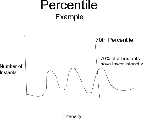
Percentile
click the image for an enlarged diagram.
The percentile program only requires a single parameter, and that is the percentile at which the light will turn on/off - we'll call that p. It makes two passes through the audio file - the first to determine the cutoff intensity that corresponds to the desired percentile, and the second to actually record the instants at which the intensity exceeds or falls short of the cutoff.
- Looping through the song an instant at a time, find the cutoff intensity at which p percent of all instants in the song have lower intensity (that is, the p percentile).
- Load an instant from the file
- If the light is off and the current intensity exceeds the cutoff, record this instant in the song as a light turned on.
- If the light is on and the current intensity is below the cutoff, record this instant in the song as a light turned off.
- Loop up to step 2 until there are no more samples left in the file to be processed.
- If the light is on, record the last instant in the song as the light turning off, so we end with all lights off.
What is Digital Signal Processing? - The Theory
Wikipedia's Definition
Digital signal processing (DSP) is the study of signals in a digital representation and the processing methods of these signals.
What does this Mean??
The acronym DSP has two meanings - it both refers to the process of digital signal processing, and can refer to specific integrated circuits that perform signal processing (digital signal processors). In this project, we're discussing the "processing" rather than the "processor" definition (though we certainly could have used a DSP hardware to speed sound analysis). Digital signal processing is analysis and modification (through "filters") of a signal stream represented as a digitized analog signal.
Advantages of DSP
Versatility:
- digital systems are capable of being reprogrammed for use in other applications
- digital systems are capable of being ported to different hardware
Repeatability:
- digital systems may be easily duplicated
- digital systems do not depend on strict component tolerances
- digital system responses do not drift with temperature
Simplicity:
- many things are done more easily with digital systems as opposed to analogue systems
Limitations of DSP
- Aliasing results from sampling: there is no distinction between high and low frequencies
- Limited frequency resolution results from limited duration of sampling: there is no distinction between any adjacent frequencies
- Quantisation error results from limited precision (word length) when doing conversion between analogue and digital forms, storing data, or performing arithmetic
Brief Definitions
- Aliasing is when one frequency looks like another (e.q. a high frequency looks like a low frequency).
- The ability to resolve adjacent frequencies (the difference between two frequencies) depends on the length of time that is used to sample the signals. This is known as frequency resolution.
- Both aliasing and frequency are limitations that arise from mathematics which cannot be overcome.
- Quantisation error is the result of errors due to limited word length when measuring and processing the signal.
- Quantisation error can be improved by increasing the word length used.
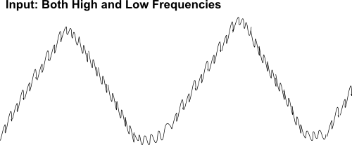
What is a Filter?
A filter used signal processing functions to remove unwanted signal components and enhance others. In our case the signal components are the frequencies. More specifically, digital filters work by performing mathematical operations on the signal components.
Advantages of Digital Filters versus Analog Filters
- A digital filter is programmable.
- Digital filters can be easily designed, tested and implemented.
- Digital filters, unlike analog filters, remain stable when it comes to time and temperature.
- Digital filters, unlike analog filters, are capable of handling low frequency signals accurately.
- Digital filters are very versatile in their ability to process signals in different ways.
Types of Filters
click the image for an enlarged diagram.
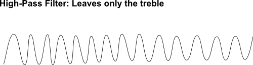
High-pass filter
A high-pass filter is a filter that allows high frequencies, but it reduces the lower frequencies. What it does is it allows you to pick a frequency, which is the cutoff frequency, and then filters out all of the frequencies that are lower than the cutoff frequency. The low-pass filter is just the opposite of this.
click the image for an enlarged diagram.
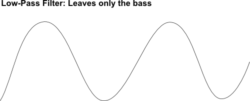
Low-pass filter
A low-pass filter is a filter that allows low frequencies, but it reduces the higher frequencies. What it does is it allows you to pick a frequency, which is called the cutoff frequency, and then filters out all of the frquencies that are higher than the cutoff frequency. This is just the opposite of the high-pass filter.
click the image for an enlarged diagram.
Band-pass filter
A band-pass filter is a filter that combines a high-pass filter and a low-pass filter. This allows you to get a filter that gets a mid-range of frequencies instead of either high frequencies or low frequencies. It reduces the frequencies that are above the high cutoff frequency and those that are below the low cutoff frequency.
Applications
- High-pass filters can be used to direct high frequencies to a tweeter speaker (loud speaker used to produce high frequencies), while blocking bass signals. The bass signals are blocked because they could cause damage to the speaker. At the same time that this is going on a low-pass filter could be used to direct low- frequencies to a woofer(loud speaker driver used to produce low frequencies).
- Both high-pass and low-pass filters are also used in digital image processing. They are used to perform transformations.
Content copyright 2006 Ryan Pavlik and Nicole O'Connell. Portions of web design 2005-2006 Ryan Pavlik. This is not an official St. Norbert College web page - opinions expressed here are those of the authors, and St. Norbert College offers no warranty or indemnity for the instructions contained here. Do not attempt to follow these instructions to duplicate the experimentation of the authors: this may expose you to dangerous electrical currents. The steps listed here are for documentation only.