Experimental component
Our hardware
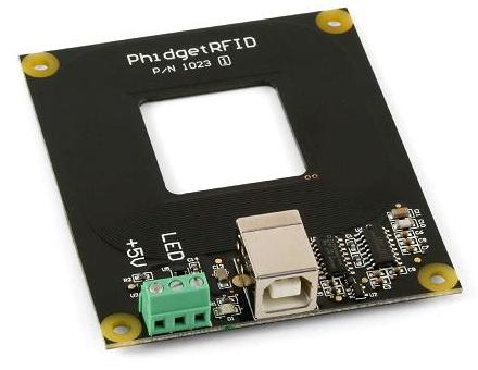
For our project, we used the PhidgetRFID board.
We selected this product because it has external outputs, is USB-bus powered which means it does not require its own power source and it has programming interfaces for a number of environments (four operating systems and eleven programming languages).
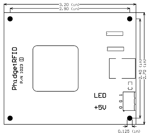
The board is small, 3.20 inches by 2.70 inches; most of the space is taken up by the antenna.
The external outputs includes:
- On board LED
- Terminal block LED
- Terminal block 5 Volt
Using the hardware
Phidget RFID connects to the computer easily with a USB cable, which is not provided, and requires that drivers be installed. A control program is provided with the drivers that can display tag IDs and toggle the outputs.
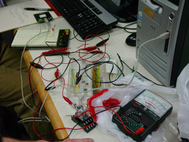
The 5 Volt output is intended to be used with either digital circuits or a relay. Using a relay requires that a fast clamping diode be used to prevent damage to the board through rectification. Unfortunately, diodes come with many different specifications and the manual does not indicate the requirements other than giving the voltage and current limit of the output.
We tested the relay and diode with using an AC-DC power adapter, but we did not test it with the board. The relay could be connected to things such as a buzzer or a light bulb.
We used both the 5 Volt output and the LED output to light two different LEDs on a breadboard.