
| Home | Journals | Images | How To | Code | Links | ||||||||||||||
This page is intended to visually show the progress being made on the TJ Pro.
Click on the images to get a closer look.
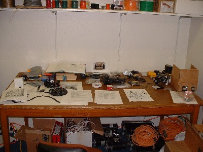
This is my work area in the Pennings Activity Center (PAC).
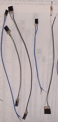
A few of the wires that were constructed for the different components of the TJ Pro.
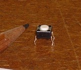
One of the four bump sensors.
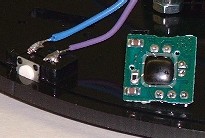
A detailed look at a IR Sensor. This sensor is roughly the size of a penny.
You see it here next to a bump sensor to get some kind of conceptual size of the wires that may need to be cut and soldered.
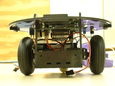
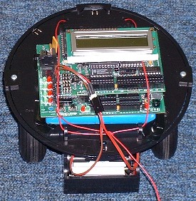
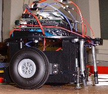
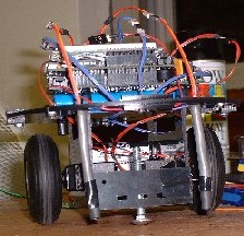
This is the front end of the partially assembled TJ Pro. It still needs IR and bump sensors.
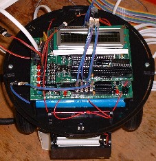
A top view of the robot on the left without the IR and bump sensors and on the right with bump sensors now.
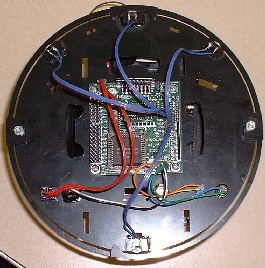
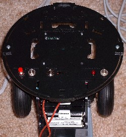
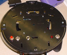
This is an underneath view of the top panel. As you can see, this is where the cpu is attached to the body.
The one on the left is without bump sensors and the one on the right shows all four bump sensors connected to the board.
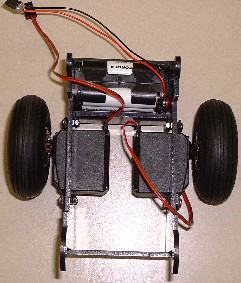
The top has been taken off to get a closer look at the battery pack and two servos motors.
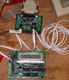
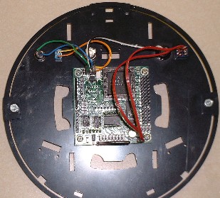
This is a picture of the Handy Board connector between the pc and board (top) and the actual Handy Board (bottom).
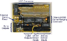
Picture schematics of the Handy Board on the left and the expansion board on the right.
This was a test run with the Handy Board temporary taped to the top of the TJ Pro. The right picture is with bumpers connected to the board.
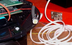
This is a picture of a single photocell. In the next pictures, the black tubing wraps around them.
Two pictures of the photosensors attached to the front side of the robot.
The actual photosensors are in the gray tubes covered by the black tubing to narrow their focus on the floor.
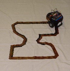
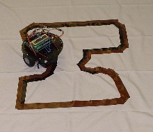
Action pictures of the robot following the line with its newly installed photosensors.