Project Journal

January 17, 2002:
Today DCP handed me the task of assembling and programming a robot called the Talrik Junior Pro (TJ Pro). The robot, though, is in pieces and waiting to be assembled. I am a little hesitant to accept the challenge initially due to my inexperience with soldering and assembling circuit boards. However, I have always found myself tinkering with pre-assembled electronics. I felt this project would suit me well and would force myself to gain in-depth knowledge of circuitry.
Once the assembly part of the project would be completed, the TJ Pro will be programmed with the language of Interactive C (IC). This language is a variant of C, but this all I know of the language so far.
Dr. Pankratz has also given me the books: Mobile Robots: Inspiration to Implementation and Robotic Explorations.
January 18, 2002:
Today, DCP and I walked over to PAC to check out where I will be working on the TJ Pro. Dr. Pankratz also gave me the key to the room so I can work in there at anytime. He also physically gave me the TJ Pro kit. I took it home and looked up the TJ Pro on the Internet at www.mrrobot.com. I downloaded the user manual and assembly manual for the robot. I also took a look at all the parts that came with the TJ Pro kit.
January 20, 2002:
In the first meeting with DCP, we discussed looking into finding an updated edition to Mobile Robots by Joseph L. Jones and Anita M. Flynn. I searched for the book on Amazon.com and found that a second edition did exist.
January 22, 2002:
I began delving into the books Dr. Pankratz provided me.
January 23, 2002:
I went over to my workshop area/room in PAC tonight to familiarize myself with soldering. I first began experimenting on a junk circuit board with wires of different sizes. It was rough at first, but I slowly began to feel confident enough to solder a few circuits to the main board of the TJ Pro. It was tedious but I managed to pull off some impressive soldering.
January 25, 2002:
Today I met with DCP to discuss how the project was going. I discussed my concern with my lack of experience with the hardware aspect of the project. Dr. Pankratz then gave me the complete works of a previous student, Joe Anderson, who worked on a similar robot last year for his capstone project. I read most of what he had written down about his robot "Elvis". After reading that, I began to soldering some wires to some plugs for the robot's power LED light.
January 27, 2002:
I took a look at the Mobile Robots again and found some useful ideas for the IR sensors. The book explained that IR sensors could be station directly pointing out either to the right or left and the other facing out at a 45 degree angle. This setup would allow the robot to follow along a wall or something similar. The book also went on to say these IR sensors could detect an object 16 inches away.
January 29, 2002:
After reading about the IR sensors in the book, I went to my work station in PAC and began looking through the assembly manual for the IR sensors. What I found was instructions on how to hack the digital output IR sensors to analog output. The diagram shown in the manual looked self-explanatory. As you can see here with this attached photo...
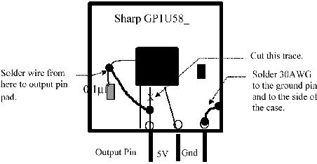
But as I pried open the metal casing around the IR sensor, it became apparent to me that this was going to be a difficult task to successfully complete. The wires shown in the diagram look to be fairly visible, but when I looked at the real IR sensor chip, the wires were minuscule. I felt the best thing to do at this point was to talk to Dr. Pankratz about this, before I dive in and screw something up.
January 30, 2002:
I was back to soldering wires to female plugs again. It's actually quite tedious work, but I'm making progress.
February 1, 2002:
I met with Dr. Pankratz this morning to discuss my findings with the IR sensors. Dr. Pankratz took a look at the problem of embedding, soldering, and cutting these tiny wires on the IR sensor chip. He had the same reaction I had to the problem and believed the task at hand was near to impossible.
He suggested that converting this digital output sensor to analog may not be needed. He explained that when I come up to an object the sensor should return a 1 to indicate there is something within its "cone of detection." The analog output may give us a depth reading but we were not sure. We also took a look at the IR sensor that was on last year's robot, made by Joe Anderson. Dr. Pankratz stated that his IR sensor never really worked that well but we took a look at it anyways. We found that he only soldered a wire from the ground pin to the metal casing. I was instructed to contact Joe for some insight to this problem.
I also had another question for DCP. I had two cpu's that came with the kit and I was confused on which cpu I was to use. He told me that he intermingled two kits in one so that I have parts from two kits. It turns out the cpu I though I would be using is not the one the actual TJ Pro kit came with.
Pankratz gave me a deadline. I am to have the TJ Pro assembled and at least moving back and forth on its own by Friday, Feb 8. This is a hefty task, but I believe it can be done.
February 3, 2002:
I found a great visual wiring assembly manual online for the TJ Pro. I went to PAC to finish up the soldering of wires but now realized that all the soldering I had done was for nothing. I had been using the wrong female plugs; they were meant to be used with the other kit for the other cpu. This is a step in reverse, but I quickly got back to work and began soldering again. Well, do not fret, the deadline will be met!
February 4, 2002:
I went to the store today and bought a can of black spray paint. However, tonight I found that I did not need to buy the spray paint. I had previously thought the color of the body was white, but it turned out to be a packaging sticker over all the body parts. It was very time consuming to remove this protective sticker off all the parts. Once I got this done, I assembled the robot's body.
After that was drying, I soldered most of the wires that are needed for the TJ Pro. I have about 3 or 4 wires left to do for tomorrow.
February 5, 2002:
I finally finished up the last of the wires tonight. Now it was time to test out the servos motors that came with the bot. Pankratz thought there may have been some motors already hacked from last year's robot. To clarify what I mean by a hacked servo motor, one must understand what a servo motor is. A servo motor is a small motor meant more for model airplanes and cars. This motor only moves back and forth to a certain degree. It is mostly designed for a rudder on plane or the steering control on a car. So these motors do not move 360 degrees. Thus they need to be hacked in order revolve in a circular motion as drive wheels on my robot.
The directions I got online from mrrobot.com were a bit difficult to understand and didn't seem to apply to the motors I was working with. I put hacking the servos motors down for tonight and worked on physically mounting the cpu to the body of the robot. I also placed a few control switches onto the body.
February 6, 2002:
Before I went to my workstation in PAC, I looked for some easier directions online to help me hack those servos motors. I found a place that provided an excellent step-by-step hack. This website can be found by following this link...Servos hack
I began to hack one of the servo motors, but the directions I found were not exactly for the motors I had. I will have to wait to talk to Pankratz on Friday about this problem.
February 7, 2002:
I took the night off to go to a job fair down in Milwaukee.
February 8, 2002:
Although my goal to get the robot up and at least moving back and forth on its own was not accomplished, I did make serious headway this week on the project. I talked with Pankratz this morning about the servos motor hack. He showed me a well put together visual step-by-step instruction manual made by Joe Anderson. His hack was much more simplistic than the hack I found on the Internet. He removed everything in the servo, except for the gears and the motor. It was explained to me by Pankratz that the hack I found on the Internet was to still maintain some control of the motor if needed. Since I do not need this, the little board inside the servo can be literally ripped out. This solves one problem.
Another problem I incurred, was the power switch. The directions say I should have a two prong power switch. The power switch that had come with kit contained three prongs. He showed me that if the switch was flipped to the right, the left prong was then live. If the switch was flipped to the left, the right prong was live. This concluded that the middle prong was the ground and either prong could be used for the live wire. This would leave one prong not used.
We also worked on getting my computer setup at my work area and he gave me Interactive C (IC) v3.1. This version of IC is windows based, compared to the DOS based version of 1.1 I received with the kit.
February 10, 2002:
I looked into getting a really cheap digital camera so I can show the world my progression and visually show you what I'm talking about. The cheapest digital camera I found was an Argus DC-1500 for $30 at Office Max. It looks like a really terrible digital camera, but I really don't need anything too fancy.
February 12, 2002:
Well I finally got the servos motors hacked tonight! I tested them out by directly wiring them to the battery pack. I also glued the wheels to the servo and screwed the motors to the body. It's looking more and more like a robot.
February 13, 2002:
I did not work on my robot tonight, but I did revamp my homepage.
February 14, 2002:
I spent my night working on soldering the wires I had pre-made to the power switch, reset switch, the on/off Red LED light, and the download/run switch. I then hooked them into the board and flip the power switch on. The Red LED light came which means I did something right! Now I need a program to see if she works.
February 16, 2002:
I purchased a digital camera today so I can now enhance my web page even further. I hope to take pictures of the robot step-by-step building process.
February 18, 2002:
Tonight I made good use of my new camera and took pictures of the robot and its components. You can view these under my image page. There will be many more images posted in the near future.
February 19, 2002:
I told Pankratz earlier in the day that I should have the robot at least moving by Thursday. So, tonight I began hooking the robot up to the computer and using IC. However, I ran into a problem with needing necessary boot up files specific to the TJ Pro. Pankratz had given me a disk with IC on it but it only included Rug Warrior files. Since I do not have the Internet yet in PAC I went over to the Coffrin labs to find the file I needed. After some searching on Mr. Robot's site I found what I was looking for. I returned to PAC only to find out I needed more files. So again I went over to Coffrin to find these files but I could not find any.
February 20, 2002:
I tried once again to find the necessary files to get this project moving. I could not find any of the files but it does look like Pankratz should have these files. Mr. Robot says they include them with the TJ Pro.
I wrote Pankratz telling him not to get his hopes up for tomorrow. Needless to say, I myself, am a little disappointed in not being able to make it move yet.
February 21, 2002:
I met with Pankratz in the morning and we found the files I needed. I also discussed with him an idea for the robot. I was thinking of mounting a wireless web cam to the robot and update the video on my web page. Although it seems rather distant in this moment in time, it would be a really nice feature.
After I met with Pankratz, I went back to my room and hooked up the robot and use the files Pankratz had just given me. They worked! Good so far... Well I just wanted to now write a simple program that would test out the motors. So, I made a program that made the wheels move in different directions so the robot would spin in a circle. I downloaded the code to the robot and flipped the run switch. SUCCESS!!! It was moving around in a circle at a dizzying pace. I stopped it and now wanted to download some more code on it, but for some reason it would not let me. IC was telling me it could not contact the board.
February 23, 2002:
I had very limited time today to work on the robot but I tried again to work on it but IC was still giving me the same error....CAN'T CONTACT THE BOARD!
February 24, 2002:
I took the robot back over to PAC to work on it. I worked on placing all four of the bump sensors on the robot. I took pictures of the bump sensors, so I should have them on the web page soon. I was also fairly courageous tonight and decided to tackle the IR sensor hack. I managed to pull off a fairly decent hack job, but only tests will show how well I did.
I did hook the robot up to the computer in PAC and ran IC. I was amazed, IC could now contact the board. But for some reason I could not get that one test program out of memory so any new code I tried placing on it never ran. TJ Pro just likes to spin around and around.
February 25, 2002:
I had a meeting with Dr. Pankratz this morning about my current situation with the robot. We ran a number of tests on trying to clear the memory, place a new piece of code in memory to run, toggle the download/run switch, etc. We both concluded that this is out of our hands right now and that I should contact Mr. Robot and Joe Anderson about it.
February 26, 2002:
I emailed Mr. Robot's message board but found out later tonight that I cannot email their message board without being a member. I am now signed up to be a member, but the email verification letter is not going through. I also emailed mekatronix, the makers of the TJ Pro and other robots Mr. Robot handles, and Joe Anderson.
February 27, 2002:
Jack from Mekatronix emailed me back, but his answer did not help my current status with the robot. I replied to his email.
Since I've not been able to do much with my robot, I've been doing some remodeling with my web page. My biggest accomplishment tonight was customizing the scroll bars.
February 28, 2002:
Jack replied back to my email, but he still did not answer my problem, so I replied. He emailed me back latter today to tell me to unload the program and to read the manual. This was explained all in the first message to him about why I cannot unload the program. So I got nowhere with Mekatronix's help.
March 1, 2002:
I got a reply back from Joe Anderson who told me that if I leave the board unplugged with no power, it should forget all data. He estimated it should take a day for it to lose all stored memory. My board has been unplugged since Monday. Hopefully he is correct.
March 3, 2002:
I went over to PAC today to see what I could do with the robot. I was really hoping it had lost all of its memory in the course of its six day power outage. But of course that was not the case, the robot behaved just as it had done on Monday. I tried once again to load/unload code, but this did nothing. I even got so desperate to use the buggy DOS version of IC. This did not work either.
March 6, 2002:
I presented my project/problem to the rest of the class. They provided me with some helpful tips to try to resolve my problem but later that night I worked on it again getting the same results as before. Round and Round it goes!
Since this current board is not working Dr. Pankratz, after a short meeting after class yesterday, told me to educate myself with a new board called the "Handy Board." So, I educated myself with the Handy Board, and prepped the board for demonstration to Dr. Pankratz for tomorrow morning's meeting.
March 7, 2002:
I met with Dr. Pankratz this morning to discuss progress made on the Handy Board. The meeting went well, and I was able to load and unload different programs. All of these programs ran as well. I am very ecstatic that I have a fully functioning board. The only drawback to this board is the size of it. You can visually see this for yourself at my image page.
March 9 - March 17, 2002: SPRING BREAK
March 17, 2002:
I worked on soldering new wires to fit the handy board. Once I got the wires for the motors done I hooked them up and ran a few test programs out to see how it handled. I noticed that the right wheel was a little more powerful than the left. I fixed the problem by reducing the right motor to 95% the power of the left motor. I arrived at this by testing different speeds out on the right motor while I had the left motor spinning at 100%.
March 20, 2002:
Tonight I worked on writing a program that would make the robot move in a square like pattern and come back to the same spot it started out at. It works fairly well, so I hope to improve on it with added sensors.
March 24, 2002:
I worked on soldering new wires for my bump sensors so they can properly attach to the Handy Board.
March 25, 2002:
Now that I have all the bump sensors attached to the Handy Board, I am ready to run a few test programs. I first created a test program to tell me which, if any, bump sensors were triggered. If a sensor(s) was/were hit, I had the program display "RIGHT" or "CENTER n RIGHT" etc. After running a few successful tests with the test program, I moved on to making the robot react to each sensor. If the robot was hit in the front, I made it stop, put it in reverse, turned it either to the left or right, and then proceeded to move forward again until another sensor was hit.
March 27, 2002:
I met with Dr. Pankratz this morning to discuss the progress I have made so far and where I need to go from here. He liked what I programs I demonstrated to him, but told me he would like to see another sensor on the robot soon. This way I can do something else than bump detection, and I can also write some multitasking code. Another observation I made this morning was that I could multitask with the four bump sensors already in place on the robot. For example, if the front-center bump sensor was triggered, the robot stops then backs up. Currently the robot is not checking right away to see if the back bump sensor would be hit while backing up.
This can be easily solved by calling a bump function, where the robot is constantly checking for a hit. Once a hit occurs, the immediate action would be to stop the wheels. Then I would proceed to take a corresponding action to the bumper that was triggered. Prior to taking this action, I would need to release the CPU from the bump function so that the CPU could tell if another sensor was hit.
April 1, 2002:
Tonight I worked on soldering new wires for two light sensors which I will be installing on the front of the TJ Pro. For right now though, I temporarily have them taped to the front for some initial testing. I used an old program made by Joe Anderson last year to test out their capability to follow a line. The initial tests didn't work very well. I changed the spread of detecting light which improved the overall performance. What I mean by changing the spread of light values is when the light sensors are picking up light, the function will return a numerical value. This numerical value will be low when there is a substantial amount of light and very high when there is close to no light. So...when I changed the spread between when it's light to when it's dark, the robot still went off course a few times due to its own shadow.
April 2, 2002:
I worked on improving the design and accuracy of my light sensors by placing tubing around the sensors. This focuses the light sensors to a specific area. I also developed a multitasking bump sensor program.
April 3, 2002:
I met with Dr. Pankratz this morning and he did like the light sensors following a pre-made track, but told me that my multitasking bump sensor program didn't really multitask. I was also using the "sleep" command which blocks the CPU for a specified time (this is not multitasking).
April 7 - 14, 2002:
I'm going to group all these days together, because I worked everyday on my robot and ended each day with the same results, frustration.
This week I have been going to my chamber in PAC and working on developing a multitasking piece of code that will make the robot autonomous. (I should be placing a code page to this web page soon) The code I have been trying to write is running the robot in some default direction and when an event occurs, like a bump sensor was hit, the robot will react accordingly. The code I had early on would call a function called cruise first. This function would run the robot in a default direction; I had it set to go forward. When a bumper was hit, say the Center bumper, I programmed the robot to stop for .5 sec, then move back for 1 sec, then turn right for 1 sec., and then continue to cruise. Now, say the Center bumper was hit and while it was going backwards the back bumper was triggered. If this were the case, my robot/code should now exit the center bump routine and handle the back bumper code.
I am no longer using the sleep command to let the motors move in a direction for x amount of time. I am using a function called wait.
This wait function will be sent a time value. If the current time + time value sent is greater than the current time, stay in the while loop and defer the CPU if another action occurs.
void wait(int milli_seconds) {

		   long timer;

		   timer = mseconds() + (long) milli_seconds;

		   while(timer > mseconds()) {

		     defer();

		   }

		}
However, my earlier programs did not handle a bump sensor being hit then another one being pressed while the first bump segment of code was executing, so it was not multitasking.
I have been examining Joe Anderson's code from last year to see how he overcame this difficulty. He and Pankratz did not use the wait function like I am using, but a global variable called delay, placed in the cruise function. The delay variable would then be set when a bump occurred so the cruise function would not execute for the given amount of time. My later versions of this same piece of code involved using the delay function. This did prove to be an improvement because the robot was now recognizing multiple bumpers being hit, so it was now multitasking. So it should be working right? My robot decided to deny me again and decided not to run any of the motor commands like stop, backup, and turn right. All it did was stop for however long the delay was, then resumed cruise. This is where I am at right now with my robot. I've lately been getting the urge to throw it out my third story window.
I also met with Dr. Pankratz this week to discuss my current situation and to troubleshoot and brainstorm around this obstacle.
April 15 - 21, 2002:
It's been a busy week and I've fallen behind on my journal, so I am again going to lump a week's worth of journal entries into one.
At the beginning of the week, I was again having problems multitasking with my four bump sensors. I talked to Dr. Pankratz again on Wednesday. I implemented the wait function like we had discussed before, but my bumpers were executing all their code without interruption. Pankratz immediately saw a problem with my code implementation. I was using a single bump function with a imbedded if..else.. in a while loop. This proved to be problematic because when a bump occurred, the entire bump function was locked in the if statement. The wait function was not my problem.
We concluded that I needed separate functions for each bumper. This implementation would allow for multitasking because when a bump occurs the wait function would be called thus releasing the CPU to check if another event (bump) occurs.
I worked on the idea that night and within a half-an-hour the idea became a reality. I was now multitasking! Now that I was multitasking with the bumpers, I began to include my photocells into the overall code. It took a good hour to incorporate the photo sensors into the code and work out a few syntax errors. But, it meshed well with my bump sensor code and I now have preemptive multitasking code for following a line and detecting objects in it's path.
April 16 - 28, 2002:
Ahhh yes, the home stretch. This week has proved to be the most busy and productive week of my college career. This week I constructed a little maze/arena out of wood for Kasper. I've conducted my bump testing in this arena and learned something new about my initial bump code setup. When I was bumping into a wall on the right bumper then turning and hitting the center bumper my code instructs the motors to turn right, so I was caught in an infinite loop. This was easily solved by placing a previous bumper variable as the direction of the center bump function. Let me break it down in simpler form. If the right bumper is hit I make the robot go to the left because there is something blocking it on the right. I also set "previousbump = left" because this is where I want Kasper to continue moving if the center bumper gets hit (and vise versa for the left bumper).
I have also made new code where Kasper can follow a flashlight on the floor directly in front of it. This will help display the multiple capabilities of the photocells. I also replaced my left servo motor because it was starting to give me troubles. The last thing I want is a burned out motor causing the death of my presentation.
One thing that I thought I may improve but proved otherwise, was my line follow track. It was initially made out of black electrical tape, but after multiple tests I found that the tape sometimes slowed up the robot due to it being slightly elevate from the paper. So, I thought if I constructed a track with black permanent marker this would solved this problem. However, it did not. The black marker idea actually turned out to be worse. For some reason, the black marker left behind a rather sticky finished which in turn left Kasper's back roller entrenched in its filth. Oh well, back to the tape track.