CS460
Computer Controlled Railroad
with Multiple
Cars
Erik Riggenbach
Computer Science Major
Senior at St
Norbert College


|
Controlling the Trains |
||||||||||
|
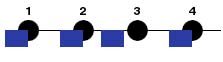
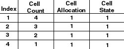
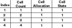
The trains are moved about the track by issuing commands which the engines receive. Each train engine has an address and a set of commands which it has built into its chip. I used a function which Jeremy Vosters created last year. MyDCC_motor (ID, Dir, Speed) is the command that I used to get the trains moving. Getting the trains to move was pretty easy once I was able to figure out the libraries and what .dll files needed to be included. ccr.dll, dp.lib, dcc.lib were the .dll and .lib files I needed to include. In addition to these, I used the MyDcc.cpp and .h files Jeremy created last year and his ResourceManager.h. These files make interfacing with the train possible. The first thing I did was to make a program which simply moved the train. Until I figured out the allocation and the count of the photocells I didn't try to move the train backwards. I simply needed a way of knowing what the train was doing. Plus, if I am to allocate cells, I also need to de-allocate them. Other wise, when I try to grab it again (on a circular path for example), I would be unable to do so. I used a text file as a batch. This allowed the train to get another instruction when it accomplished it's goal. The file has 4 fields, photocell requested, speed, direction and instruction. So, a command of 3 4 1 0 would be translated into request photocell 3 at speed 4 going clockwise around the track and it's a normal command. The 0 at the end means it's not a special command. If that number is a 2 the train should perform a decoupling when it reaches the photocell requested. If that number is a 3, the train should perform a coupling when reaching the requested photocell. The direction flag, 0 is counterclockwise, and 1 is clockwise. A sample file can be found here. I needed a way to know which photocells were connected to which. I decided to use a 2 dimensional array which would work like a linked list. The index of this array represents the specific photocell. When a photocell is requested, the program checks the array for the cell it currently has and sees which photocells are Connected to the current photocell. The first 2 columns of the array represent possible photocells. The third column represents turnouts that are in-between the two cells. If the photocell requested is found in the first column then the turnout must be turned to on. If the photocell requested is found in the second column, then the turnout must be turned off. The off and on of a turnout is simple a way of turning the turnout one direction or another. The turnouts are not all set up uniformly, I think some of them were put on backwards. This is the reason for the data structure. The data file which stores this track layout is found here. The first se of data is for a clockwise direction around the track. The second set of data is for a counter-clockwise direction around the track.
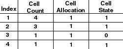
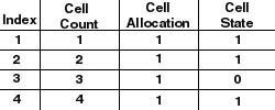
Backing up proved to be somewhat of a problem. I think I got caught up in trying to make the train move forward properly and did not think about the needs of switching directions. I needed to be able to upon switching directions make the system think the train was always going in that direction. The main problem with this was making the count as if the train had been going in that direction. There were two possibilities for a cell's count. If the train was covered, the count would equal (train's length +1)- current count. If the cell was not covered, the count would switch to train's length - Current count.
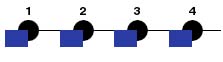
When I reversed the train, rather than simply switching the direction the motor was spinning at, I stopped the train for about a second or so. This allowed the motor to come to a rest. The hope here is to increases the motor's life by not causing strain on it. The movement of the trains is approximate. When a command is given for the train to move at a speed of 4, the train moves about 4. This is due to several conditions: the track's dirtiness, the motor's dirtiness, the power on the track, and the wheel friction on the track all change. This means that on one section of the track a speed of 4 is a bit slower than on another. The only problem I had with this was when I was going to uncouple and couple the cars. This only became a problem because I had to stop the train over a magnet in the track that is about 2 inches long. This has to happen consistently. On the coupling of the cars, I have to make sure that the car parks over this magnet without the couplers being over the magnet itself. Errors in this positioning, can cause the train to fail on either of these tasks.
|