CS460
Computer Controlled Railroad
with Multiple
Cars
Erik Riggenbach
Computer Science Major
Senior at St
Norbert College

|
Photo Cells |
|
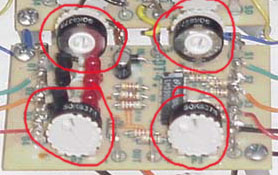
This is what proved to be the heart of the project. Without being able to allocate and de allocate photocells, the rest is pretty much impossible. I went through several models of how I wanted to represent the layout with data structures. Finally I decided to go with 3 arrays of a length equal to the total number of photocells. The idea was to poll the cells one by one and handle arrivals and departures as they happen. Later this presented a problem because I was trying to evaluate a constantly changing situation by only looking at part of it at a time. This meant that by the time I got around to looking at a photocell, several events may have happened before I was able to do anything about them. So, I was forced adopt a 4th array so that I could in a sense take a snap shot of the state of the board. And then do a comparison of the cells past state with the current one. I end up polling all the cells, that is seeing if they are covered or not. This information is stored into an array called current state. I then compare this information with the previous state (stored in another array). I adjust the counters for the photocell at this time as well. I have a link to a page with diagrams of a train with length 3 passing over a series of 4 photocells (possibly long load time). This hopefully will show the process of allocating cells when a train hits the cell for the first time. Each consecutive car simply ups the count. When the train hits a cell for the first time, it requests the next cell in line. If this cell is available, it is granted to the train at this time. Other wise, the train is blocked (see Blocking). When a car leaves a cell, the program checks to see if the full length of the train has passed over the cell. If that is the case, the previous cell is de-allocated. In step nine of the flow chart, photocell one is de-allocated after the train passes by photocell 2. There are some things that need to be done before the train allocation algorithm will work. These cells need to be calibrated to the light in the room. This can be done with the little white wheels on the photocell circuit boards. They simple are turned one way or the other to get a more sensitive cell or a less sensitive cell. More sensitivity will cause them to be tripped much easier while less sensitivity will make them harder to trip. These boards are found on the pullout shelves in the wooden cabinet. Below is a picture of these wheels.
I was forced to put a tape skirt around the base of the train so that the light would no come in under the train and trip the cell multiple times for each car. Some cars would blink two times, some once and others three times, so there was no real way to make the program recognize what a car was without these skirts. |


