|
Over the past two days, I have put a lot of effort towards defining the protocol by which all of the pieces of my application communicate.
0 Comments
tI've added the ability to read in a railyard layout from a file! The file format is relatively simple right now, and some of the functionality for the view portion of my project is not yet present, but the implementation for reading the file is extensible and it will be able to handle the additional features when the time comes. With that being said, take a look at this example of a .rail file that can be read into my simulation: 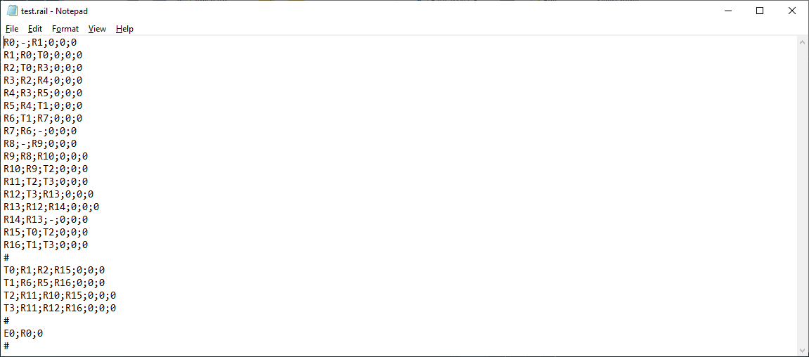 Example .rail file The file is split into three sections, separated by "#" marks. The three sections are the rails section, the turnouts section, and the trains section. Let's go through some examples of a line in each of these sections. The "Rails" SectionAs of right now, lines in the "rails" section follow the format 'rail_id;connectionA;connectionB;orientation;x;y'. Currently, the orientation, x, and y fields are unused, but they will be implemented later alongside the view component. Look at the first line in the "rails" section of the file: R0;-;R1;0;0;0. This means that Rail #0 has a connection with Rail #1. ('-' means that the rail does not have a connection on that side.) This section ends upon reading the first '#'. The "Turnouts" SectionThe "turnouts" section follows a similar but different format from that of the "rails" section. Each line here has the format 'turnout_id;baseRail;straightRail;curvedRail;orientation;x;y', where the turnout_id is the ID of the current turnout, baseRail is the id of the rail connected to the 'input' portion of the turnout, straightRail is the rail connected to the 'straight' portion of the turnout', and curvedRail is the rail connected to the 'curved' portion of the turnout. So, in the above file, Turnout #0 has Rail #1 as its base rail, Rail #2 as its straight rail, and Rail #15 as its curved rail. This section ends upon reading the second '#'. The "Trains" Section The "trains" section has a relatively simple format compared to the other two. Each line consists of the trainID (E is for 'engine'), the ID of the rail the train is on, and the train's speed (trainID;railID;trainSpeed). This will likely be extended to include things like whether the train's horns and lights are enabled in the future. The '#' at the end of this section also denotes the end of the file. Reading In The FileTo actually read in the information from the file, my program does the following:
ConclusionAnyway, that is a little bit of information on what a .rail file is and how my program reads them in. I hope that this was a clear explanation. See you next time for the next update!
Hello again! Just a quick update here: I got turnouts to work with my new rail system! They do not function exactly the same as the rails do, but with them working my rail model now functions as expected! I was able to recreate the layout that I was having trouble with in one of my more recent blog posts and it works as expected now.
The next thing on the list is to create and load rail layouts from a file and to send information back and forth between a client and the simulator server. Stay tuned for updates on that! Getting Slightly DerailedFirst of all, I would like to apologize for the late blog post this week. I spent some time last week redefining my rail, turnout, and train data models and, right when I was ready write up a post about how they worked, I found out that they didn't work. Well, that isn't completely true; they DID work, but they were missing some important functionality, so I had to go back to the drawing board. As I mentioned in this blog post way back when, the main core of the railway data model is a doubly-linked list. Each rail segment (henceforth known as just 'rail') knows what rail comes 'before' and 'after' it, turnouts are special rails that have three connections to other rails and a handful of special properties regarding their state, and trains move along these rails by following the references between them. The problem that I encountered with my data model last week is that 'before' and 'after' were a little too strong of words. In the real world, of course, your average rail has no care for direction. If the train comes in from the left side, it goes out the right, and vice versa. In my old data model, the next pointer of one rail segment would connect to the rail ahead of it and its previous pointer would connect to the rail behind it: 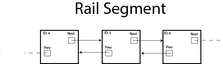 Directed Rails Example This system works great, but only if your rails read left to right. Making the train drive backwards is even easy, since you can just make it follow the 'previous' pointer instead of the 'next' one! However, if the meaning of 'forward' to a train ever changes, you are out of luck if you go this route. I was testing the following layout when I discovered this problem: 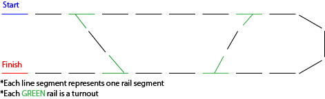 See the problem here? Maybe it will help if I add the direction of the 'next' pointers to the next rail in the layout (denoted by the orange arrows). 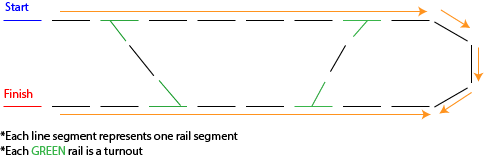 As you can see, when a train goes around the curve, it's concept of 'forward' changes, but the rail layout has an intrinsic sense of what 'forward' should be. Therefore, if the curve is attached the way it is to the rails, the train will get stuck on the boundary between the curve and the bottom straightaway. Uh oh! What Now? At first I was dumbfounded at how to fix this problem. Other people suggested that I just flip all of the pointers on the bottom straightaway so that it is one continuous segment, but what if there is another train on it whose concept of 'forward' is left-to-right? So, I decided that the best way to solve this was to make the rails directionally agnostic, and to move the burden of motion onto the train, like in real life. After a few re-works, I decided on a pretty solid system. The rails still have two pointers to their neighbors, but now they have no semantics of direction attached to them. They are simply connected to each other with up to two connections, and they will accept no more than that. (Turnouts are an exception to this rule, of course, as they need three different connections, but I am still working on those.) To compensate for this, trains now keep track of the rail that they are currently on AND the last rail that they were on. That way, when a train queries the rail it is currently on for where to go next, the rail checks its connections to see which of them is the last rail, and it returns the opposite. In simple terms, if the train came in from the left, it is sent out to the right! This complicates making a train go in reverse, but all you really have to do is send it back to the last rail it was on and use the current rail as the last rail when determining where to go from there. It's a pretty slick system, if I do say so myself. With these modifications, the "curve" problem from above is solved. The Importance of Little VictoriesTo be honest, it really got to me for a while when my direction-based rail model didn't work. For a while, I considered completely throwing away my rail-linking model and starting over using a two-dimensional array. I'm glad I didn't do that, as I'm sure it would have introduced many more unforeseen problems, but I was very close to scraping a lot of work, which would not be good what with how little time there is left until capstone presentations.
That being said, it feels so good now that I have solved the directional problem by going back and iterating on my previous solution. I will need to be doing a lot of that over the next few days in order to get this project done on time. I think I also learned a valuable lesson to not be as discouraged or to panic the next time I run into a similar problem. If I overcame this one, I can overcome the next one, too. With that said, stay tuned for the next update. There should be a lot coming in the next two weeks! Today, I figured that I would take a break from working on the desktop-application portion of my capstone and decided to take a crack at the API portion of my project before it gets too late. Truth be told, I have been a little jealous of my peers lately who have tasks like "get x login service to work" because they have very tangible results and it is always fun to get things to work together. So, I thought that working on my API would give me a taste of that feeling, and I set to work on it. The goal for today was to decide on a protocol for communication between the various pieces of my project (i.e., TCP/IP, web server that communicates via http requests, etc.), and to get a test connection set up and working between two different machines. I decided that I would like to make a REST API between my client applications and my simulation server. That way, I can pass JSON objects containing the state of the simulation back and forth via http requests. This decision was also made in an effort to homogenize my methods of communicating between applications. I am worried about using TCP/IP with Javascript, which will be important when I work on the mobile cabs for the simulator. But, I know that http requests are easy to do in Javascript and I know that they are possible in C# with similar structure, so that is why I decided on using that method for communication. So, in order to facilitate this REST API, I wrote a very simple web server using Node.js with the Express module by following this guide. I have a long way to go to refine it and develop my API in full force, but right now I have set up some logic that returns a JSON object containing info for a sample train when you make a GET request to http://johnmcgorey.com:3000/sample_train. 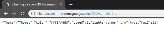 Sample GET Request The biggest challenge of today wasn't creating this web server. It was making the web server available over the internet so that I could access it from anywhere. Luckily, I have had some experience with configuring networks in the past, so I knew generally what I had to do, but it took some floundering through some port forwarding and some Windows firewall rules before I was able to access the web server (shoutout to Josh Lamack and Luke Van Vonderen for helping me through this process). It was all worth it, though, because I have a working connection now!
From here, the next steps are to flesh out the API/web server and to integrate that connection with my main desktop application and a mobile cab. One thing I would like to do is make a change in some data on the desktop that is then reflected on the mobile cab. Something I am concerned about is making the server send data to the client apps without it being requested, which might violate the principles of a REST API, but I will tackle that when I run into the issue. I might be able to find a creative way around that issue. As always, stay tuned for more updates to come! I took some time today to lay down some of the groundwork for the CCR simulator's level editor, and I just wanted to share some of the progress that I made. Most of my efforts today went towards the user interface of the level editor, but I did do a bit of preparation for allowing the user to place objects and to draw said objects (more on that later). For a brief recap, this level editor is what is going to allow a user to sketch out a "railyard" to run the trains in. It will let them place down rails, sensors, trains, and maybe more wherever they want. After everything is placed the way they like, the user can then save this "layout" and run the simulation on it. So, that's the goal. As of right now, I have a form that presents a user with five "tools" that they may use to interact with the simulator layout:
The user can select these tools by clicking on the icon for the tool on the toolbar or by pressing the corresponding key on the keyboard (i.e., 1-5). The user can deselect a tool by clicking on the icon again or by hitting the 'q' key (for quit!). When a tool is selected, a semi-transparent "ghost" image corresponding to what it does shows up under the mouse cursor. This is to give some feedback to the user about what will happen when they click the mouse. Let's look at a couple of these ghosts:  Different Ghosts appear based on which tool is selected In the above GIF, I am cycling through the different options by pushing the number keys 1-5 (notice how the currently selected tool is highlighted). Each ghost that you see is trying to express what will happen when the user clicks the mouse. The rail tool currently has a thin line as ghost to show that it will place a rail, the sensor tool has a circle, the train a square, and the eraser has an empty square. The select tool probably won't end up having a ghost because it is not placing/removing anything, but it will have graphical effects to illustrate the area it is affecting, and the selected objects will be highlighted in some way. Now, just placing horizontal lines for rails isn't going to get you very far in designing a railyard, so I also allow the user to rotate the object they are going to placed by pressing the 'r' key. The ghost also rotates accordingly. In an effort to keep things simple, I am constraining rotation to 45 degree increments, so there are eight orientations that an object can be in, although only four are really useful in most cases. The result looks like this:  Rotating an Object Realistically, this eight-directional rotation might only apply to rails, as everything else sort of snaps to the rails, but we will see.
One final note: the details of a lot of things that I mentioned above are likely going to change. The shape of the ghosts will probably change, I may add more tools as I think of them, and the location of the user controls on the form may change. However, there are a lot of good ideas here that I am excited about, and I'm pretty happy with what I have accomplished with this editor so far. Anyway, that is what I have accomplished today. Here are the next steps that I have in mind:
Hello! I just wanted to give a quick update on the state of the project after this past week. Unfortunately, I was in Utah on spring break for most of the week and did not make much progress as a result. However, I did tweak my major view component a little bit and I ported it over to my main working project instead of keeping it in the prototype project. I believe that it is ready for the next phase, which will be creating the level-editor for the train simulation. Stay tuned for updates on that!
This upcoming week is relatively open for me, so I will hopefully be able to make a lot of progress on the project. I am getting nervous about the quickly-approaching deadline, so I will be making better efforts over these next few weeks to really get things done. See you next time! Over this past week, I spent a lot of time trying to create a panel for my train-rail-yard view. The goal was to create a panel where I could scale the drawings to "zoom in and out" on the view and where I could pan the image around to see different parts of the track. I thought that this would be a fun and interactive way to control the train simulator, but so far it has proven itself as quite the challenge to pull off. I started working on this view component by creating a new C# project to work in. After a few false starts, I came pretty close to my goal, but I am not quite there yet. Basically, the view works by drawing all of the graphics to a bitmap object, using the center of the bitmap as the origin point for graphical coordinates. From there, that bitmap is scaled according to a designated scale factor and drawn to the screen using a graphics object. An offset on where to place the image (which is set by a handful of mouse click & drag events) creates the panning effect. For the most part, this works how I want it to, and I think the core principles of what I have are solid, but there are a few tweaks that need to be made before I consider this component usable. For example, when you scroll the mouse wheel to increase the scale factor and "zoom in", it moves the picture relative to the top left corner rather than where you scroll. Also, I have yet to find a way to prevent the user from scrolling off of the side of the image. I tried to put limits on the image offsets so that it would not move past the sides, but this didn't work how I wanted it to. So, there is still some work yet to do on this part! Anyway, here a couple screenshots showcasing my testing project in its current state: 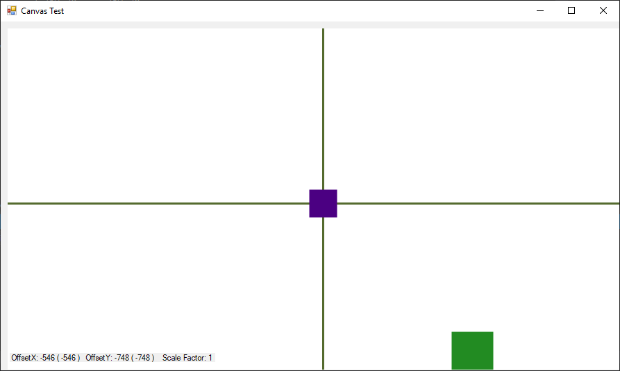 No Pan - Scale Factor 1 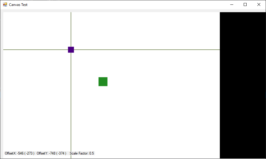 No Pan - Scale Factor 0.5 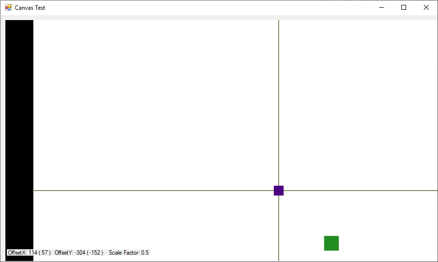 Panned up and to the left - Scale Factor 0.5 I know these pictures aren't incredibly helpful, but I hope they help give an idea of what's going on here. I tried to make some GIFs to show off the functionality, but they were moving very fast and honestly gave me motion sickness, so I chose to omit them here. Some Other ThoughtsI was looking at my Gantt chart today, and I noticed that I am behind schedule for my project. This is partially because I shifted gears to work on the view first in order to properly test the other aspects of the program, but I also poorly estimated the kind of time that I would need to accomplish some of the tasks. I will need to re-evaluate this chart and figure out how to balance my time better.
As always, stay posted for more updates! Over the course of this past week, I spent some time creating a project where I could test out my ideas for the data structures behind the simulator. Something that has been really holding me back is that I am intimidated of connecting the various pieces of my project, so I started this test off by strongly coupling two of the parts together with the intention of splitting them apart later. So, here is what I came up with this week:  Visual Demo of the Train System To offer a brief explanation of what you are seeing above, there are three trains (Thomas, Henry, and Oliver) going around a circular track consisting of 20 rails. Notice how the colored squares loop around when they reach the end of the screen. Of course, this interface is specifically tailored to this scenario, and a lot of work will need to be done to make a useful interface going forward, but this serves as a good sketch of what's going on right now.
Also important is the log at the bottom of the image. For each train in each update, the update number, train name, train number, train status, and rail is logged. This will give me an idea of what the status of the track is while I am working towards a more robust rail layout. Anyway, that is all for this update. The tasks ahead of me are to start developing a more robust layout and adding more functionality to the simulator data model. Stay tuned to see what comes next! After last week, one of my main concerns was to define the direction that I am heading in with this project. The poster sessions that we had last week made me realize that I did not have as solid of an idea of the components of the project as I thought. So, I spent some time thinking about it, and this is where I am at right now: 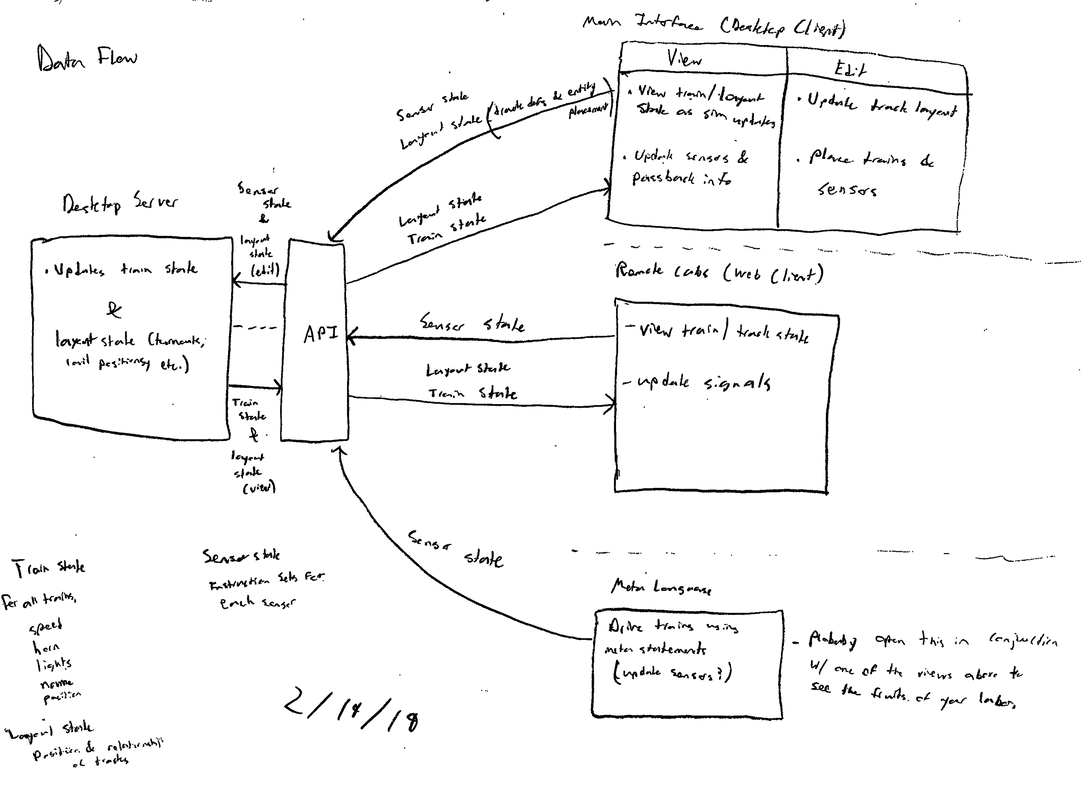 Data Flow for Off the Rails (2/19/19) Above, you see a data flow diagram for my Off the Rails project as of 2/19/19. Drawing this out really helped me to consolidate my ideas for the project, and I think I can now head in a good direction. Of course, this data flow is subject to change in the future. In fact, it may have already, but more on that later.
In any case, let me offer a brief explanation of the diagram above. Essentially, the program will be split into five parts
For the most part, these various pieces will be passing train and track info back and forth. I am concerned on how they will all stay synced up, but I will worry about that later. That's a problem I will have to solve when the various pieces actually exist. I'll see you next time with more updates! |