
My project demonstrates advanced control of the iRobot Create. There are three light sensors placed on the sides of the robot pointing outward. They are located 120 degrees apart from eachother. The position of the lights is crucial. With the lights being equally spaced out, I can accurately determine where the light source is coming from. I will go in to greater detail about the algorithm later. Another sensor that aids in the search for light is the bump sensor located in the front of the robot. If the robot receives false signals of reflected light from a wall or other object, it runs into it, stops, backs up and then continues in the proper direction.
The Set Up:
To begin from scratch to running a completed algorithm takes many steps. First, the proper compiler must be installed onto the host computer. AVRC is the language that is used for writing. Once the program is installed and ready to use, you must do a series of steps.
1) choose a COM port on your computer that will be used for sending and receiving
2) in the associated "makefile" of the .c file, be sure the AVR_PORT is set to the correct port
3) if receiving data, make sure the BAUD rate of the port is set to 115200. It is the only setting that will allow data to be received
4) install the command module to the Create. 4 screws are used and plugs into the port in the bay
5) plug in the USB cord to the Create and then to the computer
Once all these steps are completed you may now start the fun part.
Coding/Debugging:
The next step was to begin the debugging process. To do this I needed to be able to properly receive data from the Create. Thankfully, there was just enough documentation in the Command Module Manual that helped to guide me through the process. I began by sending generic data back, and then I worked my way up to light sensor data, but before I could get light sensor data working properly, I had to correctly install it.
The light sensors have to be properly fitted to one of the 4 e-ports located on the command module. Each port has 8 pins. From the documentation in the manual, I found how to properly install a light sensor to the center e-port. Each light sensor needs a 10k resistor fitted with it as well inorder to properly dial in the light reading. The first light sensor was relatively easy to install, I just went with what the manual told me. The 2nd and 3rd required a lot more research than the first. I found that the pins on each of the e-ports are completely different. All 4 ports have pins that can be used for I/O, but they are located in different spots. Also, I found that the "initialize" function needed to properly set up the pins for input. I had to do considerably research and diagramming to figure out how to plug in the remaining two light sensors, and to properly initialize them. While working on the modified initialize function I found conflicts in the command module manual. There were duplicate entries for I/O pins, and some were not accounted for. This is why I had to do lots of diagramming. Through trial and error I determined the proper pins for my sensors and then set them up correctly in the initialize.
Design of Hardware:
primitive design of hardware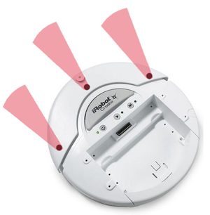
Initially, I had cones around the light sensors to amplify the light intensity being received by the sensors. This had the reverse effect. The sensors only picked up light if it was within the 30 degree opening of the cones. I soon scrapped that idea and went with no external mounting for the lights. As I stated before, I positioned them at 120 degree intervals. In addition to having them faced outward, I also pointed them slightly upward towards the center of the robot. This allowed two sensors to be affected by the light at all times. With this achievement, I was able to move along with testing my algorithm.
early design of hardware 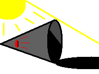
The Algorithm:
The algorithm used was created with the help of Dr. Pankratz. There are a few steps involved. First, I had to find which light sensor had the lowest level of light. Once I found this, I could conclude that the light source had to be betweeen the remaining two light sensors. The rest of the algorithm takes the two readings from the remaining sensors and with a formula, comes up with a direction for the robot to head. An example of the how the algorithm works can be illustrated as follows.
If the back left sensor is determined to be the minimum, the following code is executed.
if (posC == min)
........direction = 120 * (posB/(posA + posB));
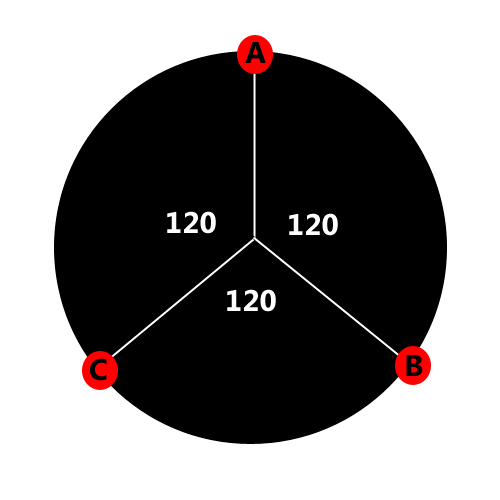 This formula would result in a direction between 0 and 120 degrees. The light source is between A and B. If the intensity of A is much greater than B, then the source is closer to A and the direction will be closer to 0. If the intensity of B is much greater than A, it will be closer to 120. If the two are similar, the direction will be near 60 degrees.
What happens if it bumps into something? This was actually a quite simple task once I finally got my hands dirty. It requires polling the sensor to see if it has been bumped. Once you poll it you immediately ask for the data back. I stored this data in a variable until I was ready to use it. When it bumps, it stops, backs up and then runs the function "findmax()." This function is used in other parts of the algorithm when I need to find the highest intensity of light.
Fine Tuning:
Once I had my algorithm running, it was time to fine tune it. I did this with hundreds of trials, testing different thresholds each time. I incorporated the direction into the drive function. Here is an example of this.
drive(0,100,255,(uint8_t)direction);
This line of code tells the robot to drive at a velocity of 100 and to turn left using the direction as the intensity of the left turn. I did this in varying degrees across my algorithm depending on whether the light was near straight or completely the wrong direction.
Using a boolean variable, my algorithm, once it is known that the light source is near straight, avoids any false readings of extreme directions. For example, if the light sources is going between -30 and +30 degrees and it jumps inexplicably high to 60 degrees or so, it ignores the reading. If it consistently gets high readings, it will eventually turn around and head in the new direction. This technique smoothed out the path it took once it had a good fix on the light source.
The current algorithm does not run well when the contrast of lighting is small. It does best when the room is dark and the light sources is bright. I do not know if the hardware is capable of solving this problem. I struggled to use software to solve the problem, but to no avail. The speed at which the robot moves was also not a factor in my algorithm. In order to properly use speed more sensors would be needed. It is not completely accurate to use the light sources to judge distance. Ultrasonic sensors would work best, and would allow the robot to move faster when the light sources was far away and slower when it was closer.