Note that clicking on the image will enlarge it.
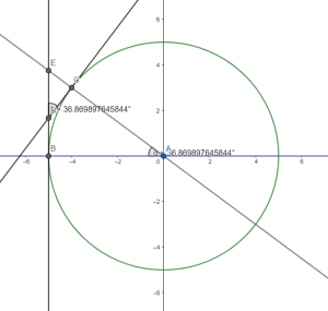
This image is particularly important to the movement physics of the lawn mower. In order to explain how, let me first give detailed layout of what this represents in respect to the lawn mower.
Point A: Right Tire.
Point B: Left Tire.
Point C: New Left Tire Position After Movement.
Segment AB: The Axle Between the Tires.
Circle with Radius AB and Center A: The Motion of the Left Tire (B) Pivoting About the Right Tire (A).
Note that in this example, it only shows how the mower moves in relation to the left arm of the mower being pushed.
Now, to explain the importance of the diagram its important to understand that angle BAC is the degree by which the left tire pivoted about the right during the movement. Within Unreal, the center of the object is the only point we actually need to rotate, but the process is the same for both points. Unfortunately, since the object rotates about its center, we need to instead translate its current position to the new position. With this translation, we don’t know how much the machine actually rotated. Imagine that rather than pivoting the lawn mower, the new point is just how far we would slide it. In order to handle rotation then, we need to know how much to rotate the lawn mower to be accurate with how far we slid. This diagram is an example of a construction that shows that the actual angle of rotation is the same as the angle of rotation from the opposite tires old location to its new location. A more obvious way to think about this is that the angle of rotation of the left tire is the same as the rotation of the total object. This reason is why the diagram was constructed using the back left tire and not the center of the lawn mower, despite the fact that the center is the point I am actually working with in the Engine. The idea is that whatever rotation is applied to the back left tire is the same rotation applied to the whole mower.
As for the tangent lines to the circle, they are added to the diagram to show the direction of motion of the lawn mower. The tangent to the circle at each point is the direction of motion. The diagram is labeled with a specific angle measure to show what I am referring to, but a proof will be supplied below.
Finally, the significance of this is that I can chose an angle by which to change the objects current position and that angle will be the same for the objects rotation. This also allows me to take the angle of change between both arms individually and by combining the resultant translations and rotations of each arm together it automatically amounts to the proper path of motion.
Proof (angle BAC = angle EDC)
Consider a circle with center A and two points on the circle called B and C where C is not on the line AB.
Note that if C is on line AB either B = C or angle BAC = 180 resulting in the tangents being parallel and thus angle EDC is not defined/does not exist.
From this draw a line tangent to the circle at point B and another at point C.
Let the intersection of these two tangents be point D.
Label the intersection of line AC and BD as point E.
Consider now triangle EBA and triangle EDC.
Note that the measure of angle BEA = measure angle DEC by construction.
Recall that tangents lines are perpendicular with the line through the point of intersection and the center of the circle.
Note that if an angle is a right angle all adjacent angles are right angles.
Thus, angle EBA is a right angle since line EB is a tangent to the circle at point B.
By similar argument, angle ACD is also a right angle and therefore angle ECD is right by adjacency.
This gives two trangles EBA and EDC where the measures of angle EBA = ECD and the measures of BEA = DEC.
This therefore means that the remaining angle of both triangles must be the same since the sum of all three angles of any triangle are equal.
Therefore angle BAC = angle EDC.


