Binary Data Storage and Manipulation
Demonstrating Physical Representation and Implementation
|
Digital Logic Gates represent ways of using simple circuitry components to create input / output devices that function exactly as Boolean algebra operators. In our project, we are concerned with the specific gates / operators: AND, NAND, OR, XOR. Since we are dealing with the binary number system, there are only two possible values, 0 (off / false) and 1 (on / true). We use the near absence of voltage to represent a 0 and the presence of substantial voltage to indicate a 1. A simple logic gates takes two inputs (two electrical connections) and generates one output (one electrical connection). Each input will either be on or off, meaning it carries voltage or does not. The output will also be either on or off. A particular gate performs the algebraic function that corresponds to it's name. For example, an AND gate will generate a positive (on / true) output if and only if both of its inputs are on. If only one of its input's are on, or neither of them are, it will generate no output (false / off). Another example is the OR gate, which will generate a true output if either one, or both of it's input's are on. Each particular type of logic gate has a pre-determined set of possible input / output combinations. This set of combinations is conveniently illustrated by what is called a truth table. For example, the truth table below illustrates every possible state for a simple AND gate
Below are the truth tables for the gates that we are concerned with. We will use this truth table format throughout the rest of the website.
Detailed information about how we actually go about building each type of gate is supplied below. AND The AND gate is a basic gate type that performs the algebraic AND function. While there are several ways of creating this gate out of circuitry, we have chosen the transistor-transistor logic (TTL) method. The AND gate is built by using two transistors and at least 2 resistors, more as appropriate. The circuitry is configured as illustrated below. (Note: If you do not understand the symbols on the diagrams refer to the section entitled 'Simple Circuitry') 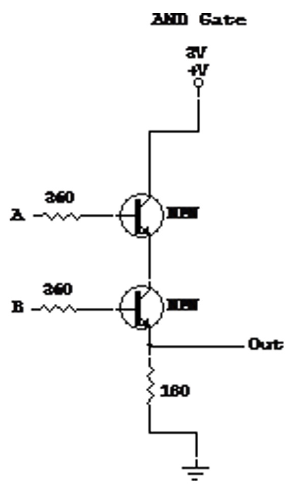 NAND The NAND gate is a basic gate type that performs the algebraic AND function and then negates the answer. While there are several ways of creating this gate out of circuitry, we have chosen the transistor-transistor logic (TTL) method. The NAND gate is built by using two transistors and at least 2 resistors, more as appropriate. The circuitry is configured as illustrated below. 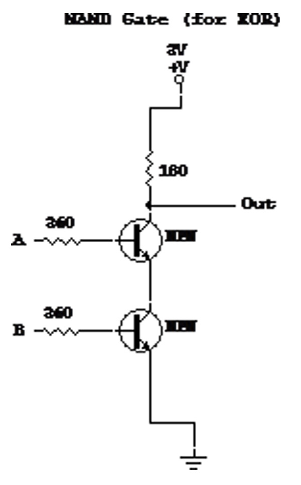 OR The OR gate is a basic gate type that performs the algebraic OR function. While there are several ways of creating this gate out of circuitry, we have chosen the transistor-transistor logic (TTL) method. The OR gate is built by using two transistors and at least 2 resistors, more as appropriate. The circuitry is configured as illustrated below.  XOR The XOR gate is a complex gate type, or derived gate, meaning that it is made by combining simple gates. While there are many ways of deriving the XOR gate, we have chosen to do so by linking 4 NAND gates. A NAND (Not AND) gate is the same as an AND gate, with the exception that, in all states, the output is the opposite as it would be in the AND gate. The XOR gate is built by combining NAND gates in the configuration shown below. 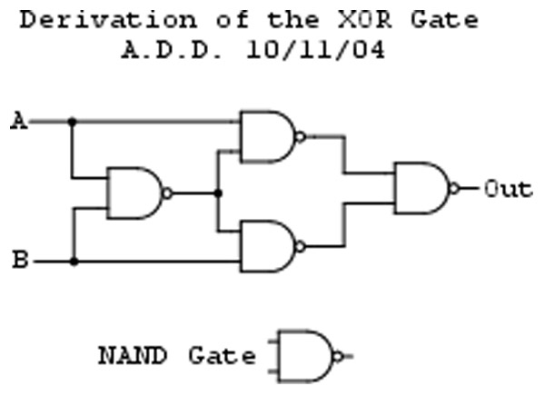 For more information about the various logic gates, such as further depth regarding exactly how and why they work and other ways of constructing them, please follow the links provided in the right pane. |
||||||||||||||||||||||||||||||||||||||||||||||||||||||||||||||||||||||||||||||||||||||||||||||
(External Link) Derived Gates (External Link) |